

BLDC vs PMSM Motors: How to Choose the Right Drive System
Author: Verna Lyu
Technical reviewer: Wen Liu, Engineer
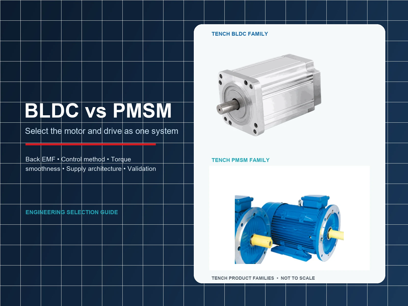
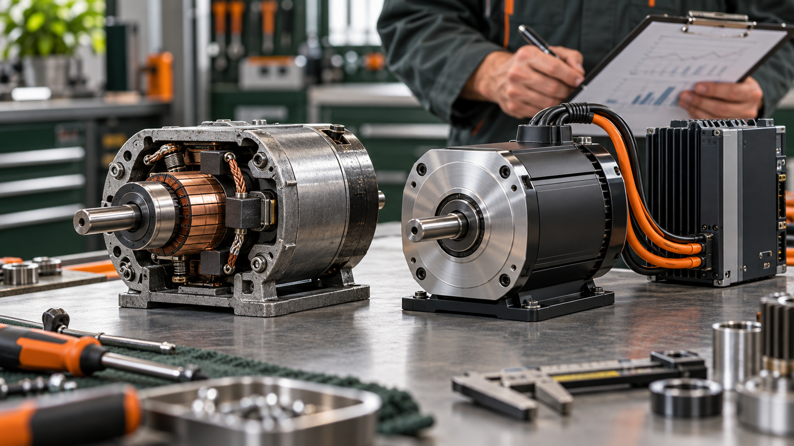
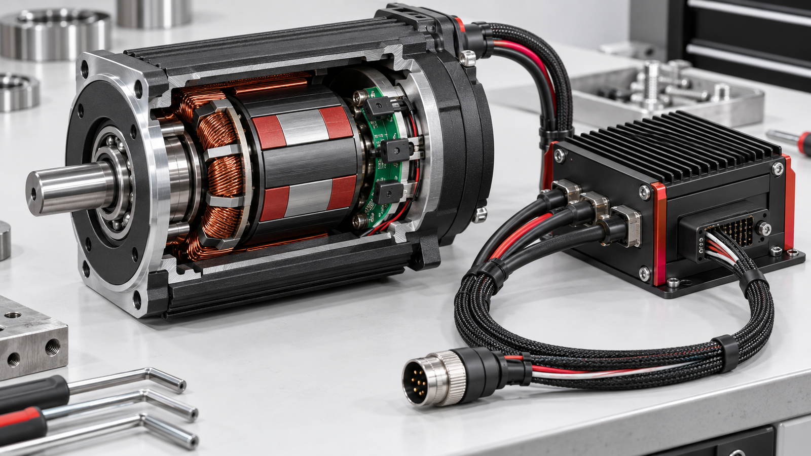
In a conventional BLDC vs PMSM comparison, the BLDC motor is designed around approximately trapezoidal back electromotive force and is commonly paired with six-step commutation. A sinusoidal permanent magnet synchronous motor is designed around approximately sinusoidal back EMF and is commonly paired with sinusoidal current control or field-oriented control. Both are permanent-magnet synchronous machines, and the boundary between the names is not consistent across every supplier.
So the name on the motor is only a starting point. An engineer cannot approve a motor from the words BLDC or PMSM alone. The motor winding, back-EMF waveform, pole count, voltage and current limits, rotor feedback, controller algorithm, speed range, thermal design and load cycle must work together. The useful comparison is between complete motor-drive systems at the required operating points.
For clarity, this article uses conventional BLDC for a permanent-magnet motor with approximately trapezoidal back EMF and sinusoidal PMSM for the sinusoidal case. Those definitions keep the comparison clear without claiming that every catalogue uses the same terminology.
BLDC vs PMSM Quick Comparison
| Selection point | Conventional BLDC | Sinusoidal PMSM | What must be verified |
|---|---|---|---|
| Machine family | Permanent-magnet synchronous machine | Permanent-magnet synchronous machine | Supplier terminology and the actual electromagnetic design |
| Typical back EMF | Approximately trapezoidal | Approximately sinusoidal | Measured or documented phase back-EMF waveform |
| Typical current waveform | Quasi-square with six-step commutation | Sinusoidal, often under vector control | Controller algorithm, current sensing and tuning |
| Torque smoothness | Commutation ripple may be more visible | Can be smoother with a suitable motor and correctly tuned drive | Measured torque, vibration and acoustic results at the real load |
| Feedback | Hall, encoder or sensorless methods are possible | Encoder, resolver, Hall or sensorless methods are possible | Startup, lowest speed, accuracy, signal compatibility and fault behavior |
| Drive complexity | Six-step control can be comparatively simple | FOC usually needs more sensing, parameters and computation | Total drive hardware, software, commissioning and validation effort |
| Efficiency | No universal advantage; the complete motor-and-drive system determines the result | No universal advantage; the complete motor-and-drive system determines the result | Test data at the required operating points and duty cycle |
| Best use | Applications that fit the available BLDC motor, feedback and controller as a validated system | Applications that fit the available PMSM motor, feedback and drive as a validated system | Exact motor and drive model, operating envelope and acceptance test |

Why BLDC and PMSM Are Often Confused
Both motor types normally place permanent magnets on the rotor and windings on the stator. The rotor follows the rotating magnetic field produced by the stator, so both operate synchronously within the scope of this comparison. A three-phase inverter can be part of either drive. The term “DC” in BLDC usually describes the supply and control tradition; the inverter still switches current among motor phases rather than applying steady DC to one winding.
Manufacturers, controller suppliers and software libraries do not always draw the same naming boundary. Texas Instruments distinguishes BLDC and PMSM by flux distribution and back-EMF profile in its trapezoidal-control application report. Microchip also notes that terminology is inconsistent and, in some material, treats both as permanent-magnet motors when the same sinusoidal control method applies. This is why a product label cannot replace electrical data.
The earlier TENCH guide How Does a BLDC Motor Work? explains electronic commutation, Hall feedback, sensorless estimation, six-step control and FOC. This article takes the next decision: when an OEM is comparing product families, what differences should determine the shortlist?
Back EMF and Current Waveform Set the Conventional Pairing
A spinning permanent-magnet rotor induces back EMF in the stator phases. Winding distribution, magnet shape, air-gap flux and other design details influence its waveform. A conventional BLDC is designed for an approximately trapezoidal back-EMF profile. When quasi-square phase current is aligned with the useful flat portion of that waveform, the drive can produce torque with relatively simple six-step commutation.
A sinusoidal PMSM is designed for a more sinusoidal back-EMF profile. Sinusoidal phase currents can then produce smoother torque, particularly when the current vector is regulated relative to rotor position. Field-oriented control is a common method, although the phrase PMSM does not by itself prove which algorithm, sensor or tuning method a particular drive uses.
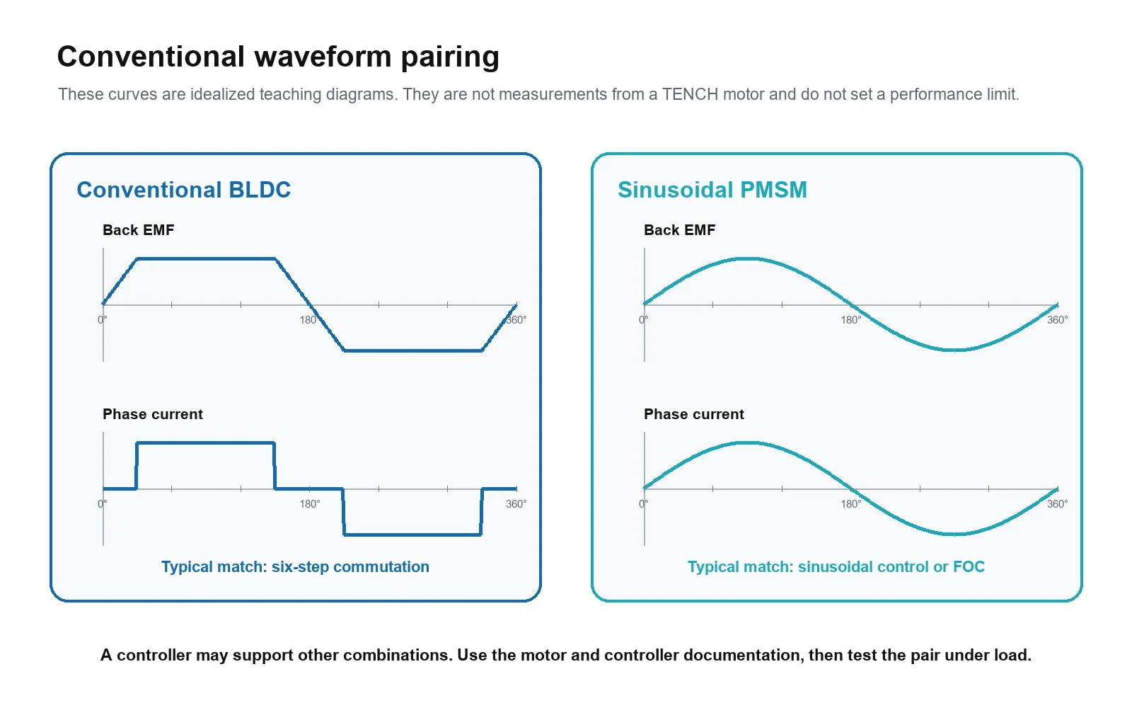
The pairing matters because torque is produced by the interaction of the rotor field and phase current. A waveform or commutation method that is poorly matched to the motor can increase torque ripple, vibration, current distortion or losses. However, that does not create a universal prohibition. Microchip documents sinusoidal control and FOC for machines described as BLDC, while ST describes six-step control for permanent-magnet three-phase motors that may be called BLDC or PMSM. The controller supplier must explicitly support the selected motor and its parameters.
Six Step Control and FOC Are Drive Choices
Six-step commutation switches among six voltage states during one electrical revolution. Hall sensors or back-EMF estimation often determine the commutation sector. It can be a sound industrial choice when loaded starting, minimum speed, torque ripple, acoustic noise and speed regulation all meet the machine requirement. Its relative simplicity can reduce controller cost and commissioning effort.
FOC regulates current components in a reference frame that rotates with the rotor field. A practical implementation normally needs phase-current measurement, rotor-angle information or an estimator, motor parameters and control-loop tuning. It can improve low-speed smoothness, torque control and dynamic response when the complete system supports it. Poor sensing, incorrect parameters or weak tuning can remove those benefits.
The same power-stage concept may appear in both systems: a three-phase bridge with current sensing and protection. Compatibility still depends on firmware, current measurement, electrical-frequency limits, rotor-position information, motor parameters and the drive's tested operating range. A controller that can physically connect to the three phases is not automatically suitable for both motors.
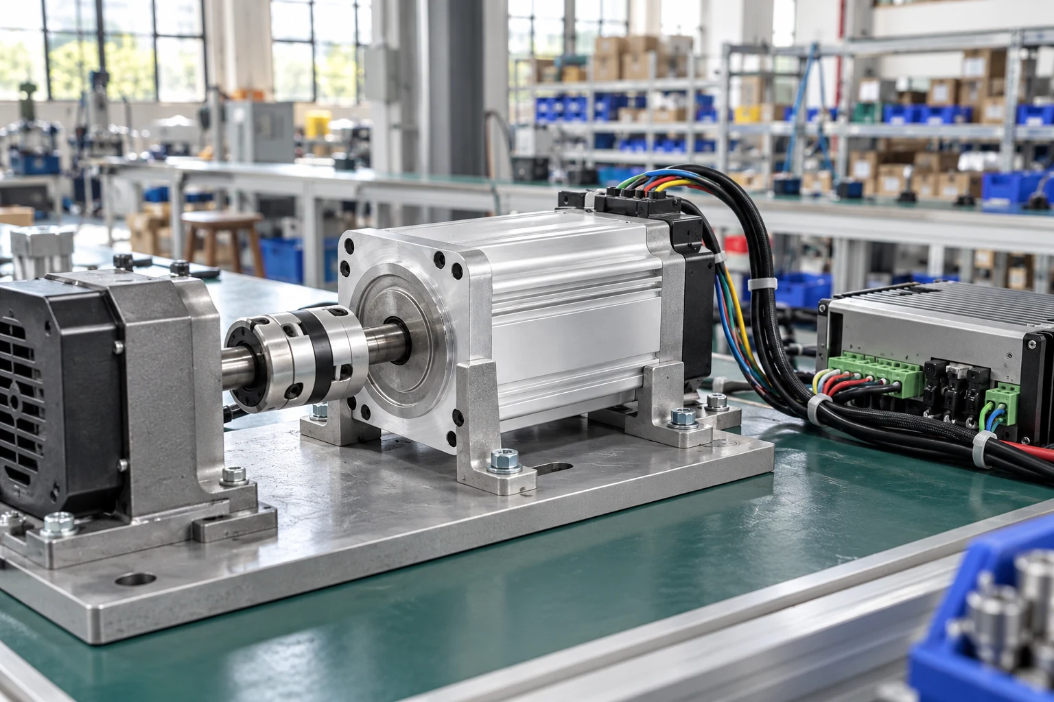
If the controller is still undecided, use the separate BLDC motor controller selection guide to check bus voltage, current definitions, feedback, braking, protection and thermal limits.
Compare Performance at the Required Operating Points
Torque Ripple and Acoustic Noise
A conventional six-step BLDC system can show torque ripple at commutation because the current vector changes in discrete sectors. The resulting vibration or tonal noise may matter in medical equipment, laboratory instruments, office machinery or precision motion. A sinusoidal PMSM with a correctly implemented drive can reduce this component of ripple.
The motor label still does not establish the measured result. Cogging torque, slot and pole geometry, current regulation, PWM strategy, mechanical resonance, bearings, gearbox, mounting and load all contribute to vibration and noise. Compare sound and vibration in the assembled machine at the speeds and loads that users will experience.
Low Speed and Starting Behavior
Hall-sensored six-step control can start a BLDC motor under load when the Hall sequence, phase order, current limit and rotor alignment are correct. Basic back-EMF sensorless control has little position information at standstill, so it needs an open-loop start and a reliable handover after back EMF becomes measurable. The acceptable starting load, reverse movement and minimum stable speed must be tested.
A PMSM can use an encoder, resolver, Hall sensors or a sensorless estimator depending on the drive and application. FOC does not automatically mean encoder feedback, and PMSM does not automatically mean precise positioning. Position accuracy comes from the complete feedback and control architecture.
Efficiency and Thermal Performance
It is unsafe to state that one motor type is always more efficient. Copper loss, core loss, magnet loss, switching loss, bearing loss, cooling and control quality change with speed and load. Six-step control may reduce computation and can use a lower switching burden in some designs; sinusoidal control can reduce current harmonics and torque ripple in a well-matched design. Neither statement provides an efficiency value for a specific machine.
Request motor-and-drive efficiency or input-power data at the actual torque-speed points. Include the power supply or rectifier when energy consumption matters. Run the full duty cycle until temperatures stabilize, because a short efficiency test does not prove continuous thermal capability.
Speed Range and Field Weakening
Maximum speed depends on the winding back EMF, DC-bus voltage, modulation limit, pole pairs, mechanical rotor limit, bearings and drive electrical frequency. Some PMSM drives use field weakening above base speed, but the permitted region and available torque are model-specific. A BLDC system may also have a broad speed range when its winding and controller are designed for it.
Do not compare only rated RPM. Record minimum continuous speed, rated operating points, maximum loaded speed, overspeed limit, time allowed above base speed and regenerative behavior during deceleration.
Eight Checks for Choosing Between BLDC and PMSM
- Define the shaft duty. Record continuous torque, peak torque and duration, speed range, acceleration, inertia, reversals, dwell time and cycles per hour.
- Fix the power architecture. State the real DC-bus or AC supply range, available current, grounding, regeneration path and any plant-voltage or battery constraints.
- Set the control target. Define whether the machine regulates speed, torque or position, including minimum stable speed, accuracy, response and allowable ripple.
- Specify startup and feedback. State the loaded-start requirement, permitted reverse motion, restart behavior and acceptable Hall, encoder, resolver or sensorless method.
- Check the motor-drive match. Confirm winding data, back EMF, phase connection, pole pairs, resistance, inductance, current definitions, controller algorithm and electrical-frequency limit.
- Check mechanics and environment. Confirm frame, shaft, mounting, gearbox, radial and axial loads, ambient temperature, cooling, ingress protection, vibration and cable length.
- Compare total system cost. Include the drive, feedback, braking hardware, filters, cabling, commissioning, software, validation and service requirements, not only the motor price.
- Approve by test. Verify starting, minimum and maximum speed, load changes, full duty cycle, temperature rise, braking, fault response, vibration, noise and EMC in representative equipment.
How the Current TENCH Product Families Differ
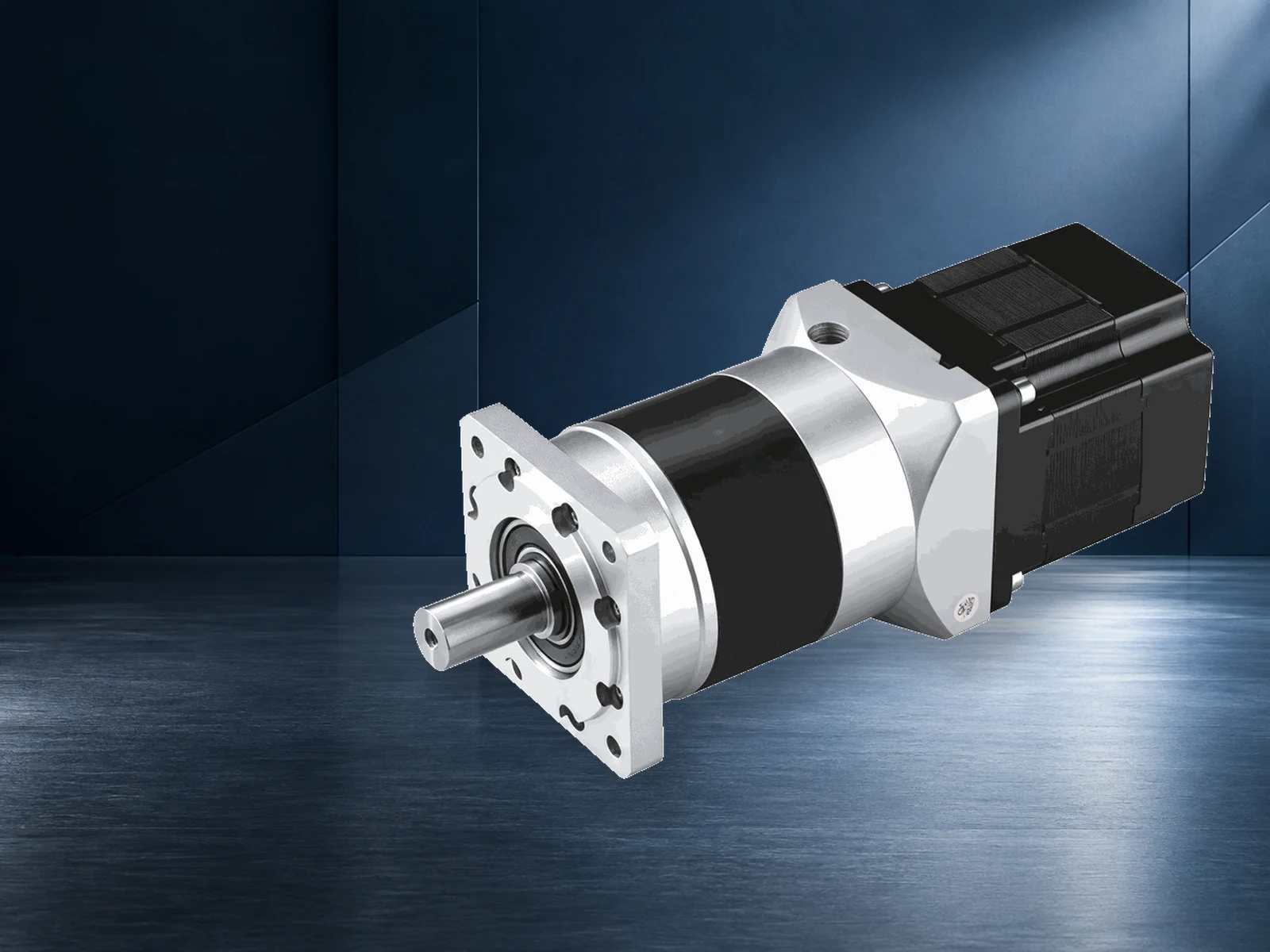
TENCH publishes BLDC motors in micro, geared and high-power categories. Individual models use different DC-bus voltages, powers, speeds, feedback arrangements and controllers. These ranges suit projects where the OEM is assembling a defined motor-drive system, including compact and geared configurations. The selected winding, drive and gearbox must be checked together.
TENCH also publishes two industrial PMSM families that have a different starting architecture and power envelope from most catalogue BLDC products:
| Published TENCH family | Published range and supply | Drive arrangement | Selection implication |
|---|---|---|---|
| Micro, geared and high-power BLDC categories | Model-specific DC voltage, power and speed ranges | Requires a compatible electronic controller or drive | Useful starting point for compact, low-voltage, geared or customized motor-drive systems; confirm the exact model |
| DYTYP variable-frequency PMSM | 5.5–160 kW, published standard voltage 380 V, 750–3,000 r/min | Powered by a compatible variable-frequency drive | Industrial plant-duty family for model-level review where its frame, power, speed, enclosure and VFD requirements fit |
| DYTY self-starting PMSM | 0.55–37 kW, published standard voltage 380 V, 750–1,500 r/min | Published for direct starting or VFD starting followed by transfer to mains-frequency operation | Industrial replacement-style family; starting method, supply and load must be verified for the exact model |
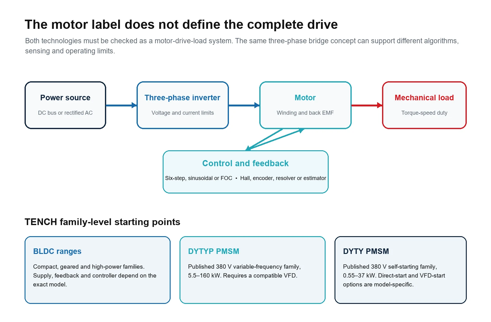
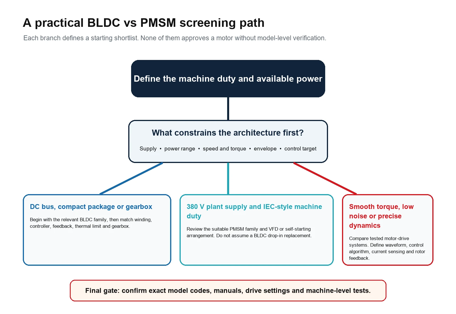
These published ranges make one boundary clear: a compact 48 V machine and a 380 V plant motor do not begin with the same electrical architecture. Likewise, a DYTYP motor and VFD are not approved by comparing kilowatts with a BLDC model. The frame, torque-speed points, starting method, cooling, enclosure, drive, harmonics, protection and installation all require a model-level review.
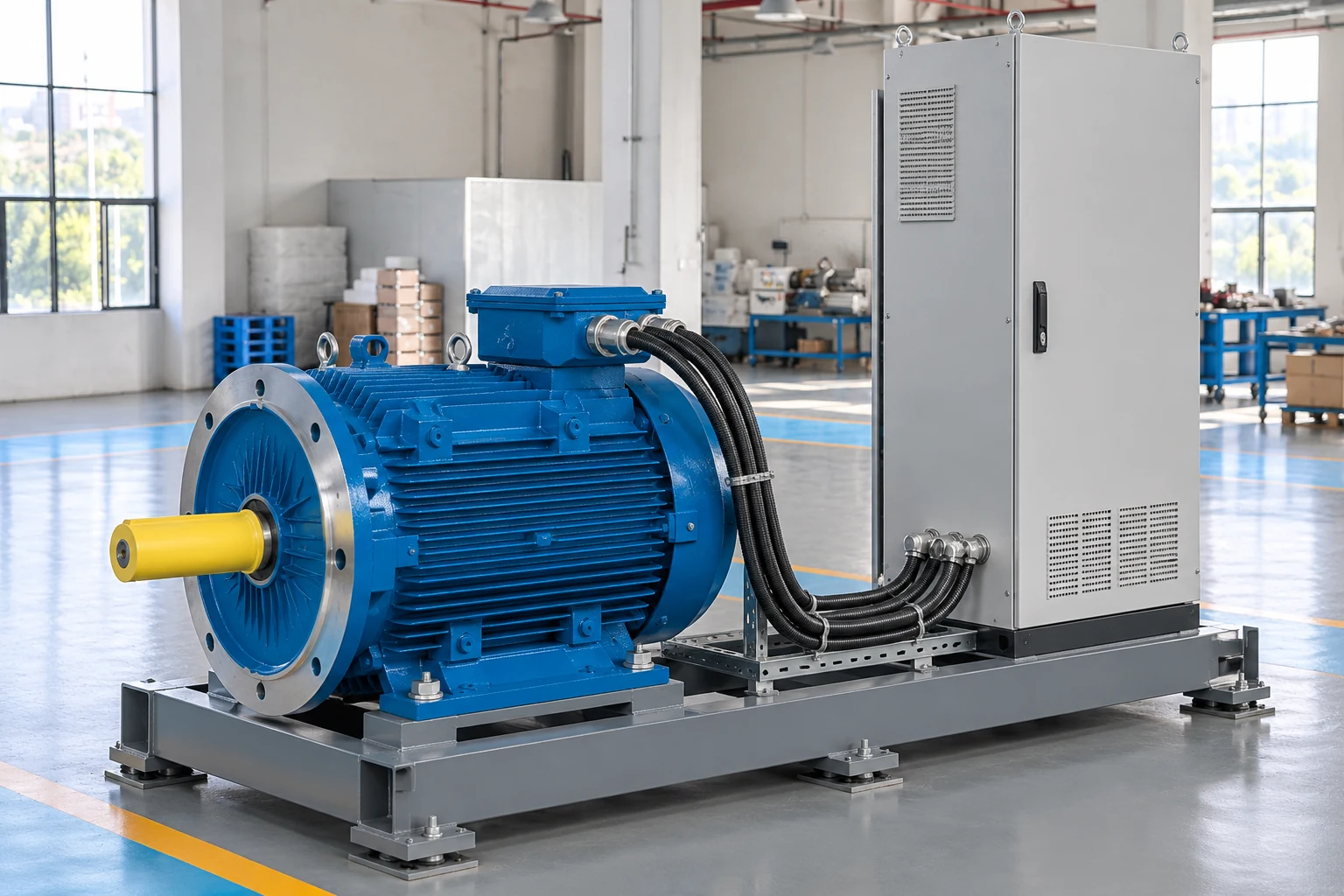
For current listings, see the TENCH high-power BLDC motor category, the micro BLDC motor and gearmotor category, the BLDC gear motor category and the permanent magnet synchronous motor category.
Two Practical Starting Points
A Battery Powered Mobile Machine
Assume the machine already has a defined low-voltage DC bus, limited installation space and a gearbox at the driven wheel or actuator. Those constraints make the relevant BLDC motor and gearmotor families a logical first review. The engineer still has to calculate the load, confirm the winding and controller, check Hall or encoder feedback, plan regenerative energy and validate temperature over the motion cycle.
A 380 V DYTYP or DYTY motor is not a direct alternative in that architecture merely because a similar mechanical power can be found in a table. Changing to it would change the supply, drive, protection, frame and integration concept.
A 380 V Continuous Duty Pump or Fan
If an industrial site has a 380 V supply and the duty is a continuous pump, fan, compressor or conveyor, the DYTYP family may justify a model-level review because the published application scope and VFD arrangement align with that environment. A DYTY self-starting model may also be considered where its starting method and fixed-frequency operation match the load.
The comparison still needs the pump or fan operating points, starting torque, inertia, speed control range, supply quality, enclosure, cooling and applicable efficiency requirements. A generic claim that PMSM is better than BLDC does not answer those questions.
Questions to Send the Motor Supplier
- What is the exact motor model, winding code, frame, shaft and mounting arrangement?
- Is the documented phase back EMF approximately trapezoidal or sinusoidal, and how is it measured?
- Which controller or VFD models and control algorithms are approved for this motor?
- What are the minimum, rated and maximum voltage and speed limits?
- How are continuous, peak and overload current defined, and for what duration and thermal condition?
- Which feedback devices and signal levels are fitted or supported?
- What torque-speed and efficiency data are available at the required operating points?
- What cooling, ambient temperature, altitude and enclosure conditions apply to the rating?
- How should braking or regenerative energy be handled?
- What tests and documents support the exact model's duty, protection, efficiency and compliance claims?
Frequently Asked Questions
Is a BLDC motor a type of PMSM?
In a broad machine taxonomy, a three-phase permanent-magnet BLDC motor can be treated as a permanent-magnet synchronous machine. In common product usage, BLDC usually identifies a design with approximately trapezoidal back EMF and six-step commutation, while PMSM usually identifies the sinusoidal case. Because suppliers use the terms differently, confirm the motor and drive data.
Can FOC control a BLDC motor?
Yes, some BLDC motors and controllers support sinusoidal control or FOC. Suitability depends on the motor's electrical parameters, back-EMF shape, current sensing, rotor-angle information, controller firmware and tuning. Do not assume that every controller marketed for FOC supports every BLDC motor.
Which is more efficient, BLDC or PMSM?
Neither name guarantees higher efficiency. Compare complete motor-and-drive data at the required torque, speed, bus voltage, switching strategy, cooling and duty cycle. A result at one operating point should not be extended to the whole map without evidence.
Does a PMSM always need an encoder?
No. PMSM drives may use an encoder, resolver, Hall sensors or sensorless estimation. The right method depends on starting load, minimum speed, torque or position accuracy, dynamics, safety and the selected drive's capabilities.
Can the same controller run a BLDC motor and a PMSM?
A common three-phase inverter power stage may support both, but the complete controller must provide the required algorithm, sensing, feedback interface, motor parameters, voltage, current and electrical-frequency range. Approval requires the controller manufacturer's guidance and a test of the exact motor-drive pair.
Which motor is better for low-speed smoothness?
A sinusoidal PMSM with correctly tuned FOC and suitable rotor-position information is often a strong starting point when smooth low-speed torque is critical. A BLDC system can also perform well with sinusoidal control or appropriate feedback. Define a measurable speed-ripple, torque-ripple, vibration or noise requirement and validate it in the machine.
What to Decide Before Requesting a Quote
The practical difference between a conventional BLDC motor and a sinusoidal PMSM begins with back-EMF design and the current waveform used by the drive. It does not end there. Supply architecture, torque-speed duty, startup, feedback, smoothness, thermal limits, drive capability and installation decide whether a specific system will work.
Start with the machine requirement and the product families that fit the available power and mechanical envelope. Then confirm the exact motor-drive combination and test it under the real duty cycle. If you are preparing an OEM project, send TENCH the supply, torque-speed points, duty cycle, control objective, feedback requirement, mounting, environment and expected quantity through the engineering enquiry form.
Technical References
- Texas Instruments, Trapezoidal Control of BLDC Motors Using Hall Effect Sensors.
- Microchip Technology, AVR447 Sinusoidal Driving of 3 Phase Permanent Magnet Motor.
- Microchip Technology, Motor Control Algorithms.
- STMicroelectronics, 3 Phase 6 Step Control.
- TENCH, DYTYP Variable Frequency Permanent Magnet Synchronous Motor.
- TENCH, DYTY Self Starting Permanent Magnet Synchronous Motor.

Leave a Reply