

How to Choose a BLDC Motor Controller for Industrial Equipment
Author: Verna Lyu
Technical reviewer: Wen Liu, Engineer
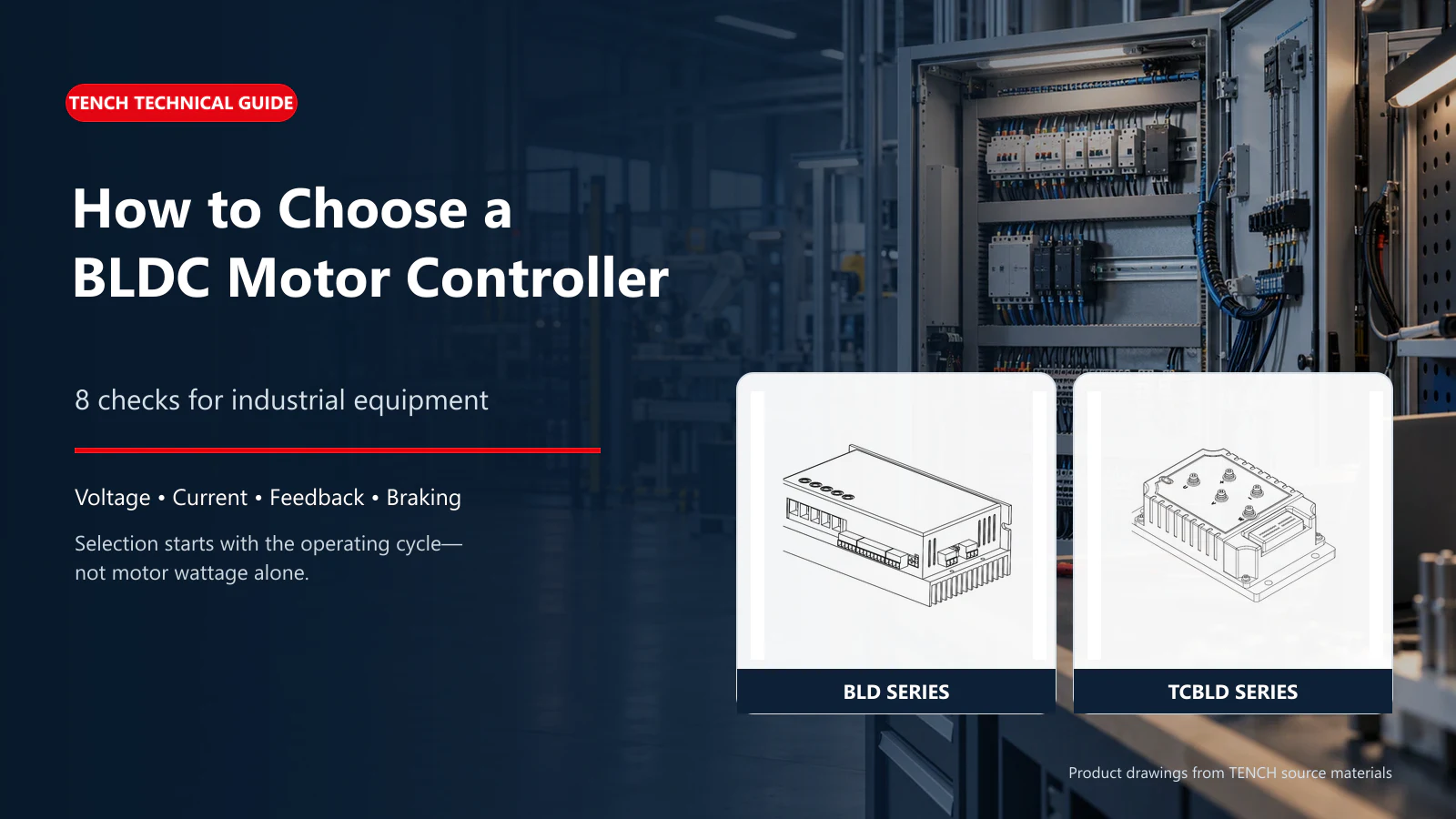
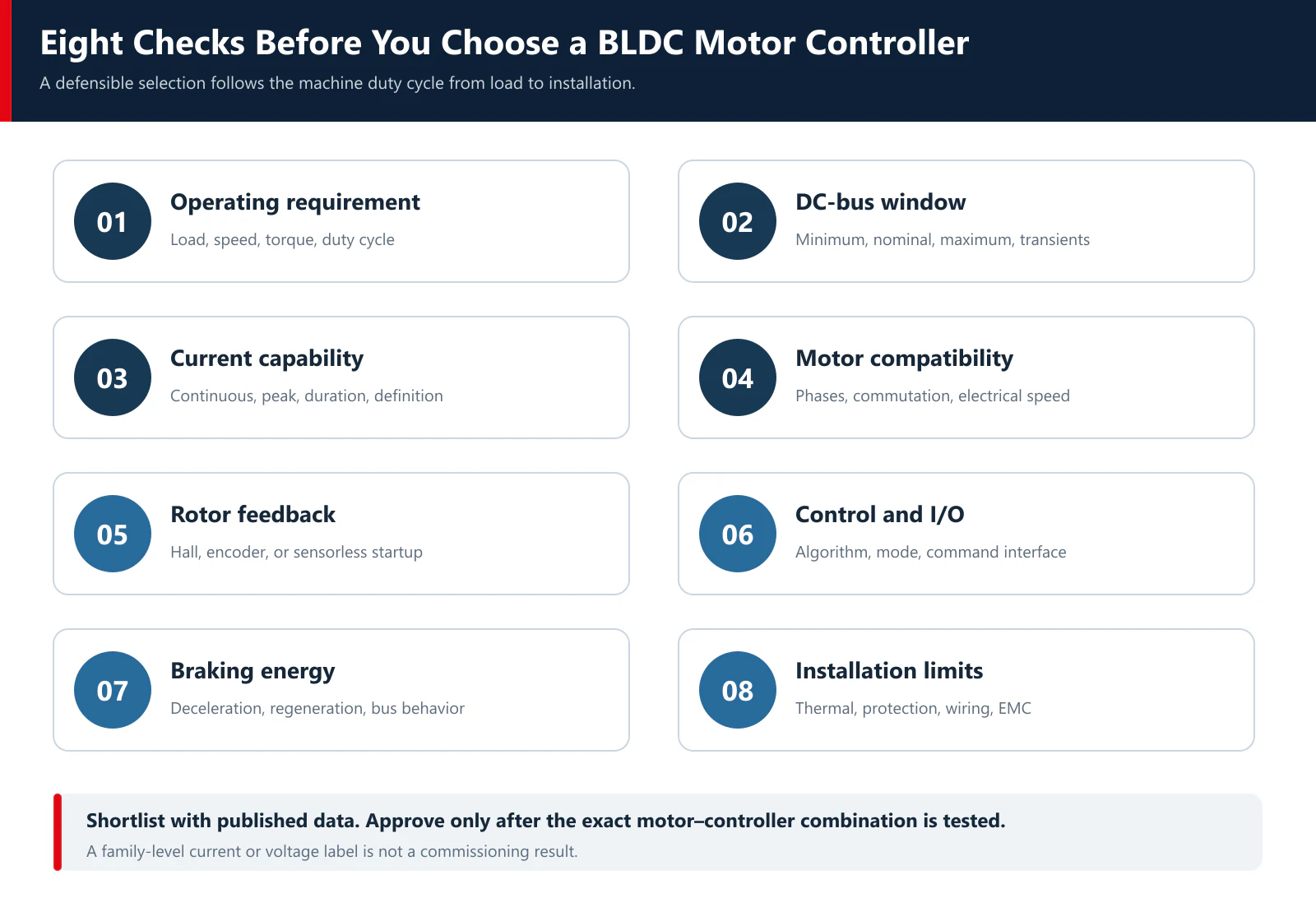
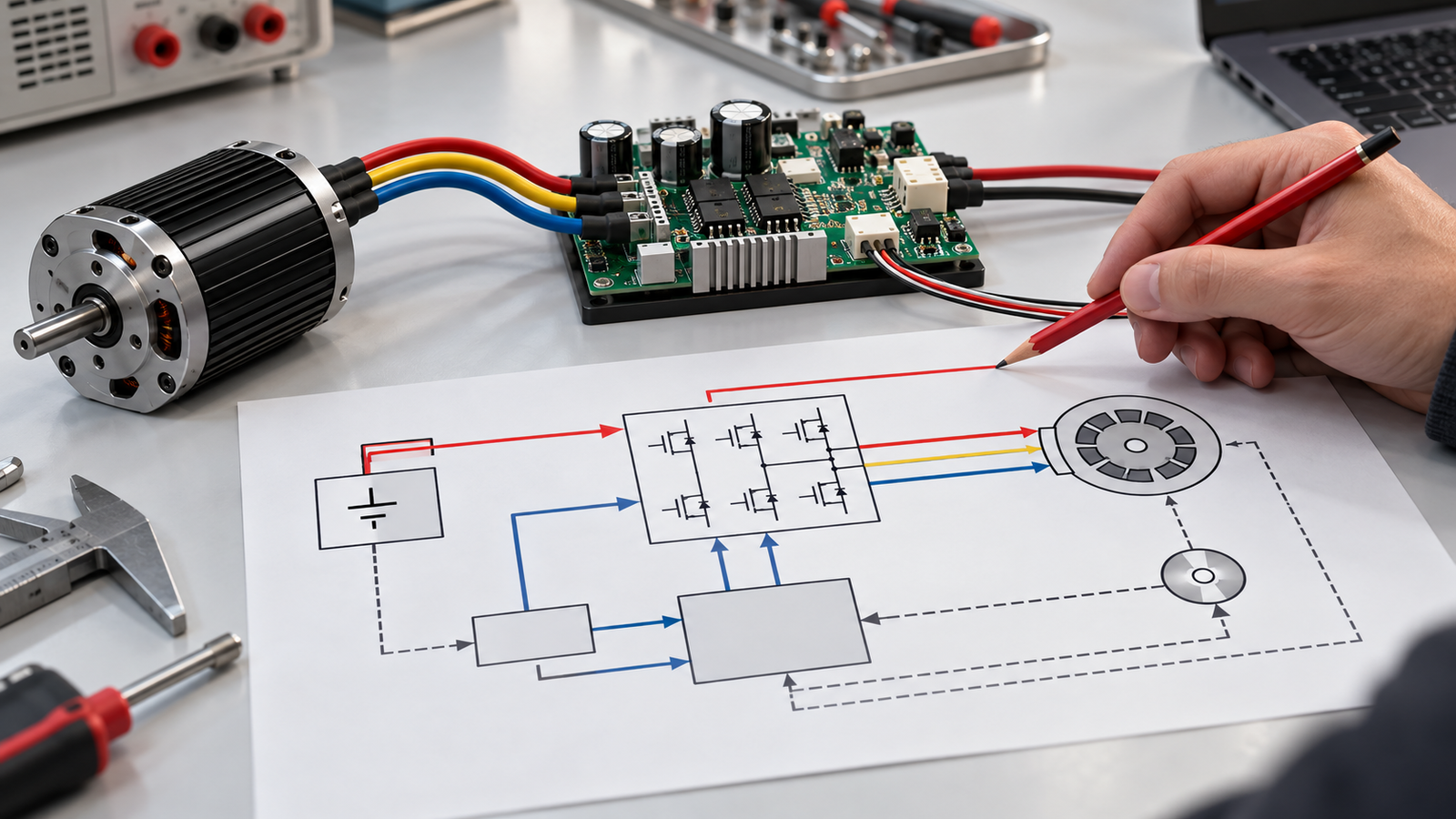
A BLDC motor controller should be selected from the operating requirement, not from motor wattage alone. Check the complete DC-bus voltage window, continuous and transient current, motor commutation and feedback, control objective, command interface, braking energy, protection, and thermal limits. Before comparing current ratings, confirm whether each value is DC-bus current, phase-current RMS, phase-current peak, or a software limit. Then test the motor and controller together under the actual motion cycle.
For a practical first pass, work through eight checks:
- Define the motor, load, speed range, motion cycle, and control objective.
- Check the minimum, nominal, and maximum DC-bus voltage.
- Match continuous current and peak current, including the permitted peak duration.
- Confirm motor, commutation, pole-count, and maximum-speed compatibility.
- Choose Hall, encoder, or sensorless feedback for the required startup and low-speed behavior.
- Match the control mode and command interface as separate decisions.
- Plan for deceleration, regenerative energy, and power-supply behavior.
- Verify thermal, environmental, protection, wiring, EMC, and commissioning requirements.
This BLDC motor controller selection process creates a shortlist. Final approval still requires the exact motor and controller manuals, a confirmed model code, correct settings, and machine-level testing.
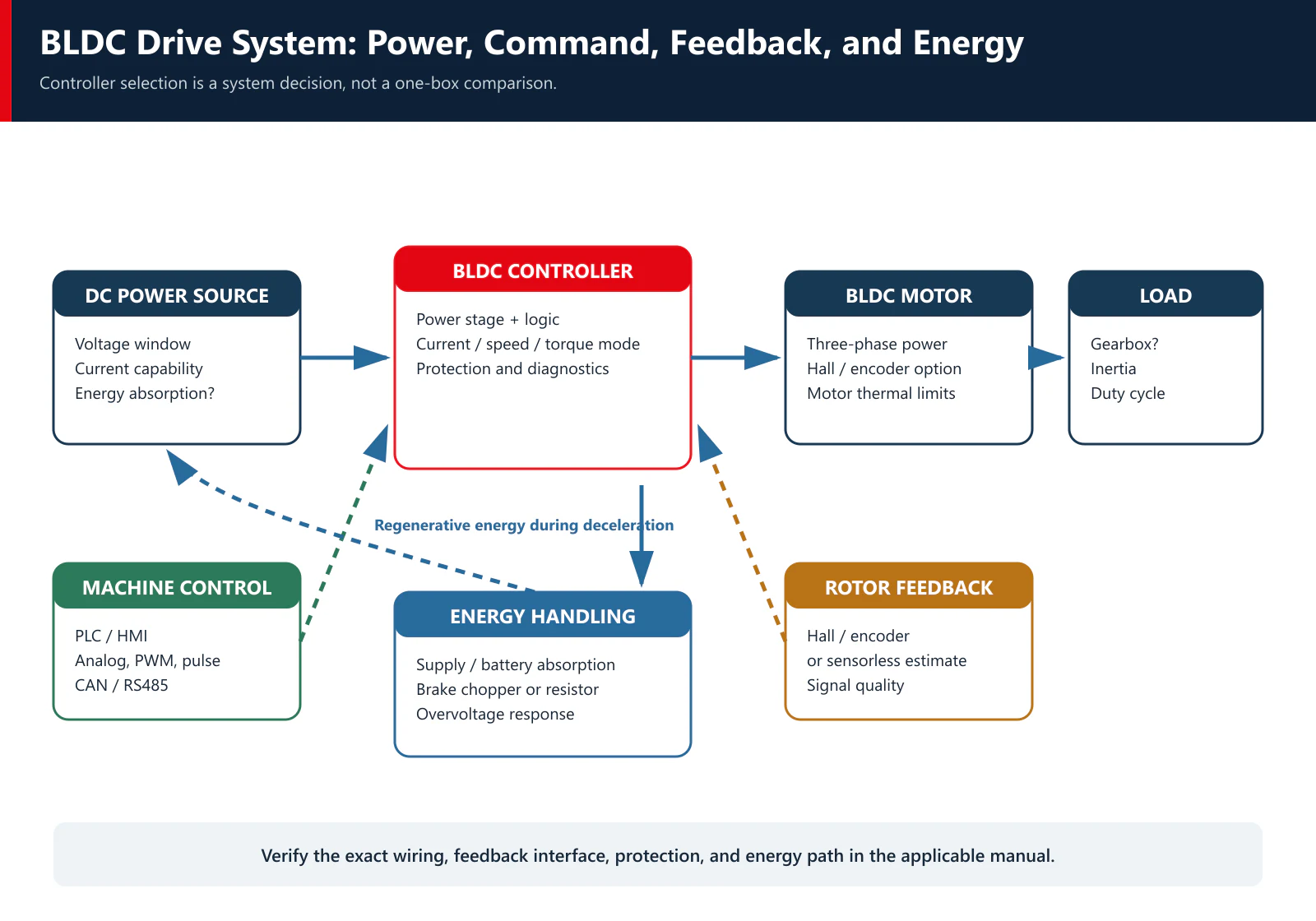
The terms BLDC motor driver, BLDC motor controller, and brushless DC motor drive are often used interchangeably for an industrial unit that combines control logic and a power stage. In component-level electronics, however, “driver” may refer only to a gate driver or power-stage function. This guide concerns complete industrial drive/controller products, not controller-board design.
Start With the Operating Requirement, Not Controller Wattage
The controller has to deliver the current needed to produce torque while maintaining enough voltage to reach the required speed. That job changes with the load, acceleration, duty cycle, cooling, and power supply. Two 750 W motors can therefore require different controller configurations.
Begin with the operating points already established during motor or gearmotor sizing:
| Required input | What to record | Why the controller needs it |
|---|---|---|
| Motor model and winding | Exact part number, winding, phase count, rated voltage, rated current, resistance, inductance, pole pairs | Establishes electrical and commutation compatibility |
| Speed range | Minimum, normal, maximum, and overspeed limit | Affects bus voltage, feedback, commutation frequency, and control method |
| Torque profile | Continuous torque, starting torque, acceleration torque, peak torque, and duration | Determines continuous current, transient current, and thermal loading |
| Motion cycle | Acceleration, run, deceleration, dwell, reversals, and cycles per hour | Defines repeated peak current and regenerative energy |
| Starting condition | Unloaded or loaded start, inertia, permitted reverse movement, required start time | Strongly affects Hall, encoder, or sensorless suitability |
| Control objective | Speed or torque regulation, accuracy, response, and minimum stable speed | Determines feedback, tuning, and control features |
| Power source | Minimum, nominal, and maximum voltage; continuous and transient current; ability to absorb energy | Sets the electrical operating window |
| Machine interface | Analog, PWM, pulse, digital I/O, CAN, RS485, PLC, or other network | Determines command and status integration |
| Environment | Ambient temperature, enclosure, dust, moisture, vibration, altitude, airflow, and cable lengths | Affects derating, mounting, cooling, and EMC |
If the load-side torque, speed, ratio, and duty cycle have not been established, complete the BLDC gearmotor sizing process first. Selecting a larger controller does not correct an undersized motor, an overloaded gearbox, or an incomplete motion profile.
Mechanical power remains a useful cross-check:
P (W) = T (N·m) × n (rpm) ÷ 9.55
It is not a controller-sizing formula by itself. The controller must also cover current during startup and acceleration, losses, bus-voltage variation, repeated braking, and the thermal conditions attached to its published ratings.
1. Check the Complete DC-Bus Voltage Window
A label such as “48 V motor” does not prove that any 48 V controller is suitable. At least four voltage questions must be answered.
Is the controller allowed to operate across the real supply range?
A battery voltage changes with state of charge, temperature, load, and charging condition. A regulated supply can droop during acceleration or shut down during overload. Record the minimum, nominal, and maximum voltage at the controller terminals, including tolerances and cable drop.
The controller's undervoltage threshold must remain below the lowest valid operating voltage. Its maximum allowed voltage and overvoltage threshold must remain above the highest bus voltage the system can produce, with the margin required by the product documentation and the application.
Is the bus voltage high enough to reach the required speed under load?
As speed rises, motor back electromotive force increases. The controller also has voltage drops and cannot always apply the full bus voltage to the motor phases. A supply can be within the controller's allowable range yet still be too low for the motor to reach the required loaded speed.
The correct check uses the motor's winding data, speed–torque requirement, controller modulation limits, voltage drop, and supply tolerance. Do not assume that matching the two nominal-voltage labels establishes the available speed.
What happens during deceleration?
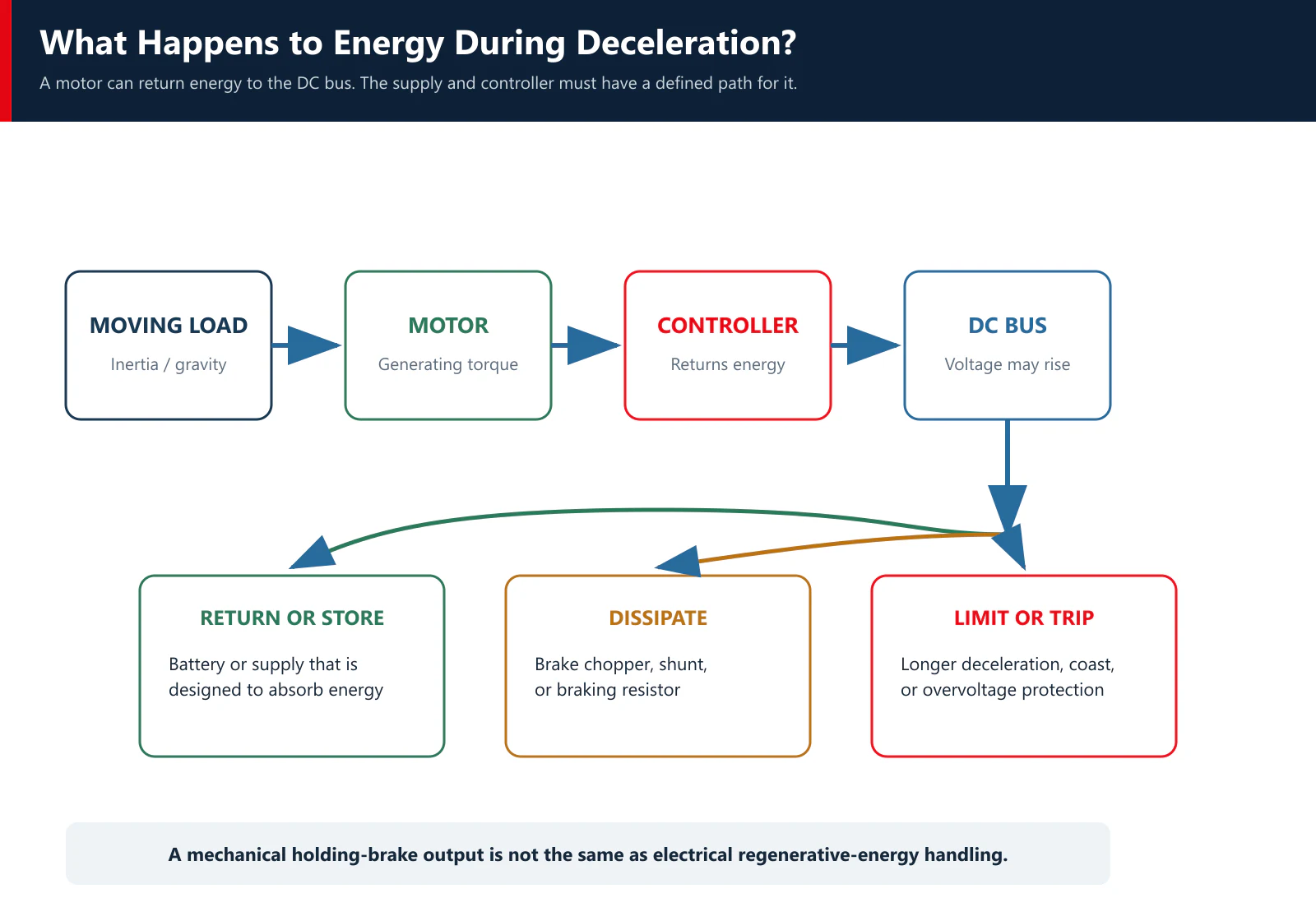
When the load drives the motor during deceleration, lowering, or overhauling operation, mechanical energy can return to the DC bus. If the source cannot absorb it, bus voltage rises. The controller may report overvoltage or disable its power stage before the machine completes a controlled stop.
Maximum bus voltage must therefore include supply tolerance, transients, and regenerative voltage rise. The power supply's nameplate value is only one part of the check.
Are the voltage names based on the same definition?
A product page may list motor rated voltage, controller rated voltage, controller maximum voltage, recommended supply voltage, or an alarm threshold. These are different values. Compare the full specifications, not identical-looking numbers.
2. Match Continuous and Peak Current Without Mixing Definitions
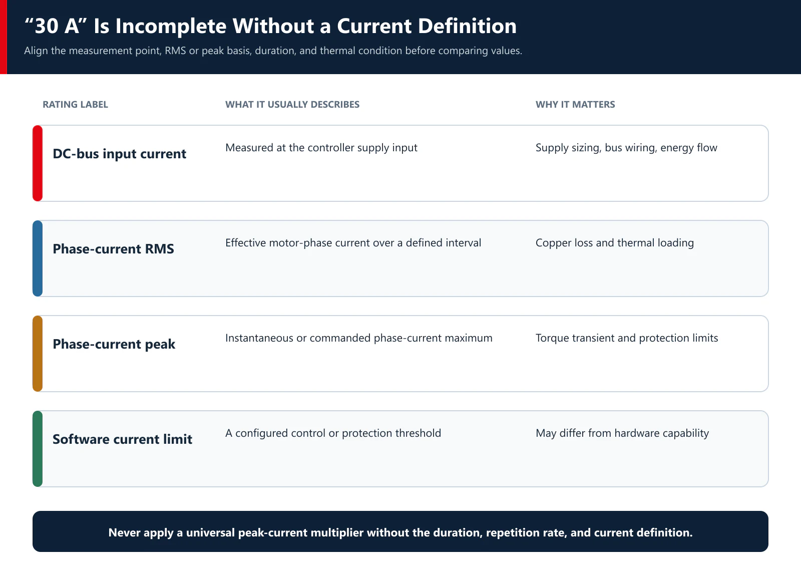
Current is the most common source of a false match because manufacturers do not always publish it on the same basis.
| Current term | What it may mean | What must be confirmed |
|---|---|---|
| DC-bus input current | Current drawn from the power source | Average or RMS basis, operating voltage, duty cycle, and measurement interval |
| Motor phase current RMS | Heating-related current in a motor phase | Commutation method, waveform, reporting convention, and cooling |
| Motor phase current peak | Instantaneous or commanded peak phase current | Peak definition, duration, switching/measurement method, and protection threshold |
| Controller continuous current | Current allowed without exceeding its thermal limit | Ambient, mounting, heat sink, airflow, enclosure, and derating |
| Controller peak or overload current | Short-duration current capability | Magnitude, allowed time, repetition rate, starting temperature, and recovery time |
| Software current limit | Configured operating limit | Whether it refers to bus or phase current and how it interacts with hardware protection |
| Hardware overcurrent limit | Device-protection threshold | Tolerance, response time, and whether it is adjustable |
The controller must support the motor's required continuous current at the actual operating point and thermal condition. It must also support the current required for starting, acceleration, disturbance rejection, and short process loads for the necessary time.
Avoid using one universal rule such as “controller peak current equals twice motor rated current.” A suitable transient margin depends on the motor torque constant, load inertia, acceleration time, friction, gearbox, current definition, controller overload curve, thermal state, and permitted voltage sag. A peak-current number without a duration and repetition rate is incomplete.
The TENCH TCBLD manual illustrates why definitions matter. It defines its rated-current parameter as DC-bus input current and separately identifies overload current, a bus-current limit, a bus overcurrent alarm, an instantaneous phase-line peak alarm, and a hardware overcurrent threshold. Those values cannot be collapsed into one generic “amps” figure.
Also check the power source. A controller may be able to command the current, but the supply, battery, connectors, cable, fuse, and contactor must deliver it without unacceptable voltage drop or overheating.
3. Confirm Motor and Commutation Compatibility
A BLDC controller switches current through the motor phases in the correct sequence and at the correct electrical angle. A BLDC motor and controller must agree on the electrical system; varying voltage alone is not enough.
Confirm at least the following:
- number of motor phases and winding connection;
- phase resistance and inductance range accepted by the controller;
- motor back-EMF and the controller's supported commutation or vector-control method;
- pole-pair count and the controller's maximum electrical frequency;
- minimum and maximum motor speed;
- Hall sequence, electrical spacing, supply voltage, logic levels, and alignment;
- encoder type, supply, signal format, resolution, index use, and maximum input frequency when an encoder is used;
- phase order, direction convention, and permitted configuration method;
- motor temperature-sensor type and input compatibility, when temperature monitoring is required.
Electrical frequency increases with motor speed and pole-pair count:
Electrical frequency (Hz) = pole pairs × mechanical speed (rpm) ÷ 60
A high-pole-count motor can reach the controller's electrical-frequency limit at a lower mechanical speed than a low-pole-count motor. This check is often missed when a controller is selected only by voltage and current.
Product labels are not enough to determine the control method. “BLDC” often refers to trapezoidal back-EMF and six-step commutation, while other permanent-magnet motors and controllers are designed for more sinusoidal excitation or field-oriented control. The boundary is not strict across every manufacturer. Use the motor and controller documentation, not the marketing name, to confirm compatibility.
For a detailed explanation of electronic commutation, see How Does a BLDC Motor Work?.
4. Choose Feedback for Startup, Low Speed, and Accuracy
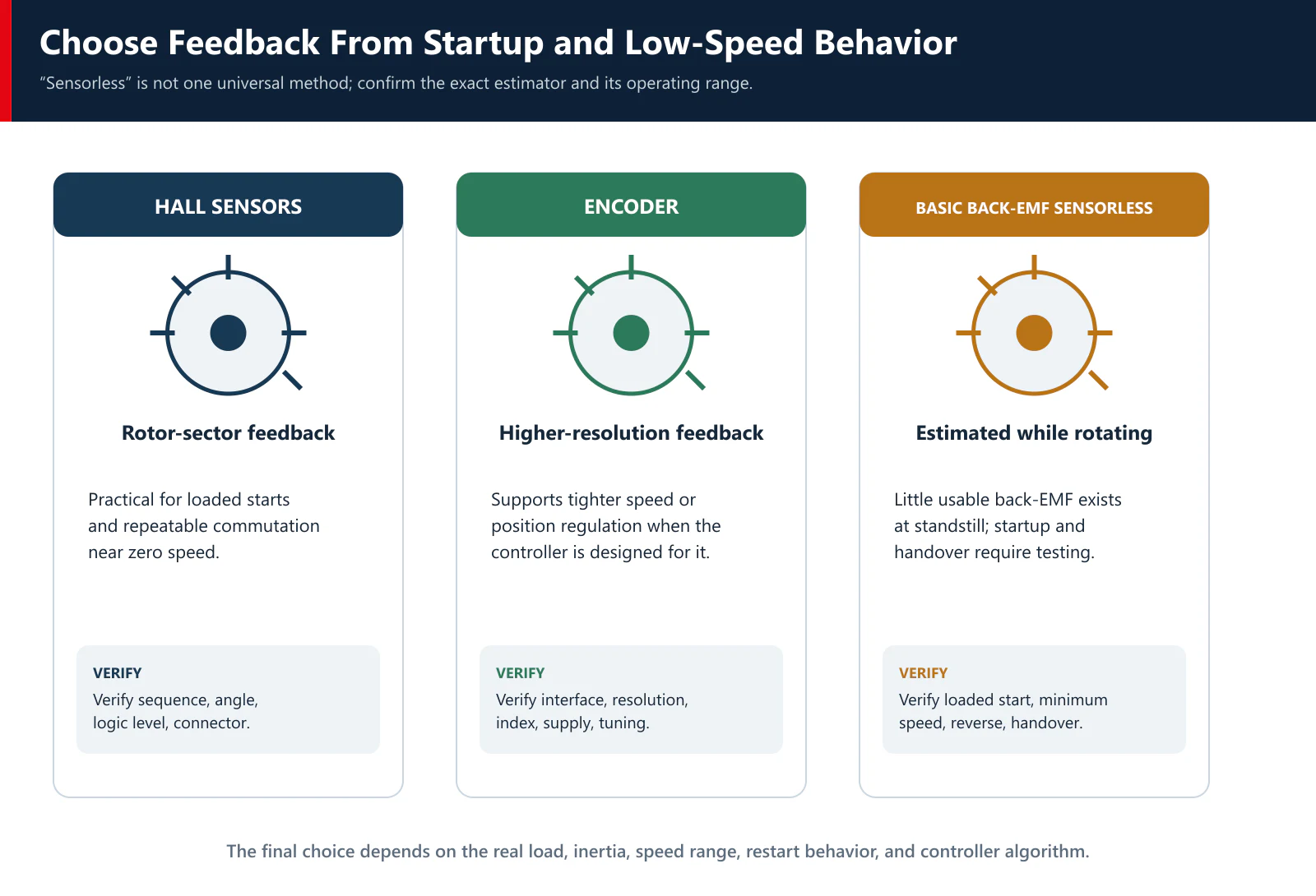
Feedback selection should begin with what the machine must do at standstill, during startup, and at its lowest operating speed.
| Position or speed source | What it provides | Best fit | Main checks |
|---|---|---|---|
| Hall sensors | Discrete rotor sectors for commutation | Loaded starting, reversing, and industrial speed control where Hall resolution is sufficient | Hall order, electrical alignment, supply, logic level, connector, noise immunity |
| Incremental or absolute encoder | Higher-resolution motion information | Tighter speed regulation or position-related functions supported by the controller | Interface, resolution, index/homing, alignment, maximum frequency, cable and shielding |
| Basic back-EMF sensorless estimation | Rotor-position timing from motor terminal voltage while rotating | Loads with controlled startup and adequate operating speed | Open-loop start, minimum reliable speed, load sensitivity, filtering, handover behavior |
| Model-based sensorless estimation | Estimated rotor angle using a motor model and measured electrical behavior | Systems supported and tuned by the selected controller | Required motor parameters, current/voltage sensing, tuning, low-speed capability |
Basic back-EMF detection has little usable signal at standstill because back-EMF rises with speed. The controller must start the motor by another method and transfer to sensorless commutation after sufficient signal is available. That transition must be tested with the real starting load and inertia.
“Sensorless” does not mean that the controller operates with no information. It means there is no dedicated mechanical rotor-position sensor. The controller still measures electrical behavior and estimates the timing it needs.
Hall sensors do not automatically provide precise shaft position. They are commonly suitable for commutation and basic speed information, but their discrete resolution may be insufficient for an application that needs fine position or very smooth low-speed control. An encoder can add information, but only when the selected controller supports the encoder type and uses it for the required control function.
5. Separate the Control Algorithm, Control Mode, and Command Interface
These three decisions are often mixed together in product descriptions. Treat them separately.
| Layer | Examples | Question it answers |
|---|---|---|
| Control algorithm | Six-step/trapezoidal, sinusoidal, field-oriented control | How does the controller regulate phase current and commutate the motor? |
| Operating mode | Speed control, torque/current control | Which physical quantity is the controller regulating? |
| Command interface | Analog voltage, PWM input, pulse, digital I/O, CAN, RS485 | How does the PLC or machine controller send commands and receive status? |
| Rotor feedback | Hall sensors, encoder, sensorless estimator | How does the controller obtain rotor position or speed information? |
An external PWM command is not the same as the high-frequency PWM used inside the inverter. A PLC may send a duty-cycle command to request speed while the controller independently generates its own switching pattern for current regulation and commutation.
Likewise, CAN or RS485 does not define the motor-control algorithm. A network interface carries commands, parameters, status, and faults. The protocol, register map, update rate, timeout behavior, termination, grounding, and machine software still need to be confirmed.
Choose the simplest interface that meets the machine requirement. A stand-alone conveyor may only need enable, direction, analog or PWM speed command, and fault output. A multi-axis vehicle or automated machine may benefit from networked commands, diagnostics, and synchronized state handling. The choice should follow the control architecture, not a preference for the longest feature list.
6. Check Braking and Regenerative Energy
Deceleration is part of controller selection, not a commissioning afterthought.
A rotating load stores kinetic energy:
E = ½ × J × ω²
where J is the total inertia referred to the motor shaft and ω is angular speed. A vertical load can also return gravitational potential energy while lowering. Faster deceleration, higher speed, and greater inertia can increase the power returned over a short time.
The returned energy may be:
- absorbed by a battery or a supply designed for bidirectional energy flow;
- shared with other loads on a correctly designed common bus;
- stored temporarily in bus capacitance;
- dissipated through a brake chopper, shunt regulator, or braking resistor;
- reduced by lengthening the deceleration ramp, when the machine cycle allows it.
A normal switching power supply may deliver current but refuse reverse current. If it cannot absorb the returned energy, the DC bus rises. The controller's overvoltage protection may then trip.
Do not confuse a mechanical holding-brake output with electrical regenerative braking. A holding-brake output controls the release or application of a mechanical brake. A brake resistor or energy-absorption circuit manages electrical energy returned to the bus. A vertical or safety-related axis may need both, plus machine-level safety measures defined by the equipment risk assessment.
TENCH's TCBLD material identifies a built-in mechanical-brake output and an optional braking-resistor configuration. The exact model, resistor value, permitted energy, wiring, and control sequence must be taken from the applicable manual and confirmed for the motion cycle.
7. Verify Thermal, Environmental, Protection, Wiring, and EMC Limits
Controller current ratings are thermal ratings. Their usable value can change with ambient temperature, mounting surface, orientation, enclosure temperature, spacing, airflow, altitude, and switching conditions. Check the exact derating information instead of assuming that a unit mounted inside a warm cabinet can deliver its catalog current continuously.
Review the installation as a complete electrical system:
- conductor size, connector current, contactor, fuse, and short-circuit protection;
- protective earth, DC-bus return, shield termination, and grounding architecture;
- separation of motor power, Hall/encoder, analog, and communication wiring;
- cable length, capacitance, common-mode current, and any required output filtering;
- enclosure IP requirement, condensation, dust, chemicals, shock, and vibration;
- airflow path and the temperature of neighboring heat-producing equipment;
- motor and controller temperature monitoring;
- overcurrent, overvoltage, undervoltage, stall, overspeed, phase/Hall, and overtemperature responses;
- safe behavior after a fault, reset, communication loss, or power interruption.
Protection names alone do not establish the safe operating envelope. Confirm the thresholds, tolerances, delay, latching behavior, reset method, and what the motor does when the power stage is disabled. Machine-level emergency stopping and functional safety require a separate risk assessment and suitable safety architecture.
EMC performance also depends on installation. A controller with a compliant test report can still cause trouble in a machine with long unshielded cables, poor bonding, shared noisy returns, or incorrect filter installation. Validate conducted and radiated behavior in the final equipment configuration.
8. Use Product-Family Data as a Shortlist, Not an Approval
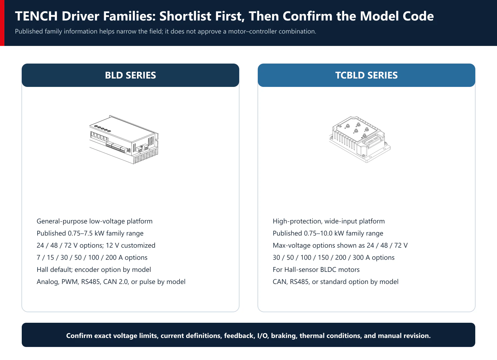
TENCH currently publishes two low-voltage brushless DC driver families. The family information is useful for initial screening, but the exact model code and manual still control the final choice.
| Published family item | BLD Series | TCBLD Series |
|---|---|---|
| Positioning | General-purpose low-voltage brushless DC driver platform | High-protection, wide-input low-voltage brushless DC driver platform |
| Published power range | 0.75–7.5 kW | 0.75–10.0 kW |
| Published voltage options | 24 / 48 / 72 V; 12 V customized | Maximum-voltage options shown as 24 / 48 / 72 V |
| Published current options | 7 / 15 / 30 / 50 / 100 / 200 A | 30 / 50 / 100 / 150 / 200 / 300 A |
| Motor feedback | Hall sensor by default; encoder option | Hall-sensor BLDC motors |
| Command/control options shown | Analog, PWM, RS485, CAN 2.0, or pulse by model code | CAN, RS485, or standard option by model code; documented I/O modes vary by configuration |
| Control functions shown | Speed and torque control | Speed and torque control |
| Braking-related item | Model-code braking-resistor option is documented | Built-in mechanical-brake output and model-code braking-resistor option are documented |
See the TENCH BLD Series Brushless DC Driver and TCBLD Series Brushless DC Driver pages for current family information.
This table does not mean that every interface or feature is present in every model. It also does not mean a published current option can be compared directly with a motor current value until both definitions and conditions are aligned.
Worked Screening Example: TC5BLD750-GU and the BLD Family
Consider the published 48 V version of the TENCH TC5BLD750-GU. Its product page lists:
- model
TC5BLD750-48GU-30S; - 48 V rated voltage;
- 750 W rated power;
- 3000 rpm rated motor speed;
- 19.53 A rated current;
- 2.39 N·m rated motor torque; and
- 7.16 N·m peak motor torque.
At family level, the BLD page includes 48 V, begins at 0.75 kW, and lists a 30 A current option. That is enough to justify a model-level review. It is not enough to approve the combination.
| Screening item | What the public data shows | Status after the paper screen |
|---|---|---|
| Voltage label | Both pages include 48 V | Candidate match; confirm min/max bus voltage and winding/controller variant |
| Power range | 750 W motor; BLD family starts at 0.75 kW | Candidate match; power alone is not approval |
| Current label | Motor page lists 19.53 A; BLD family lists 30 A option | Definition not yet aligned; do not declare a pass |
| Peak requirement | Motor page lists 7.16 N·m peak motor torque | Required peak current, duration, repetition, and driver overload curve are not published together |
| Feedback | BLD family is intended for Hall-sensor motors | Hall supply, levels, sequence, alignment, connector, and phase order still need confirmation |
| Control interface | Several BLD model-code options are published | Select the exact option required by the PLC and machine architecture |
| Braking and supply | Application-specific | Motion cycle, inertia, supply absorption, bus rise, and resistor need are unresolved |
| Thermal installation | Application-specific | Cabinet temperature, mounting, airflow, duty cycle, and cable installation are unresolved |
The paper screen should end with a shorter list of questions for the exact BLD model and the machine test plan. A simple statement that “30 A is greater than 19.53 A” would ignore the unresolved current definitions and operating conditions.
Commission the Combination Before Releasing the Machine
A controller that passes the data-sheet screen can still fail because of wiring, settings, load dynamics, thermal conditions, or regenerative energy. Use a controlled commissioning sequence.
- Confirm the motor, controller, power supply, fuse, contactor, cables, feedback device, and model codes against the drawings.
- Verify protective earth, shielding, phase wiring, Hall or encoder wiring, and signal reference before applying power.
- Start with conservative current limits and acceleration settings appropriate to the motor and load.
- Perform the first rotation at low command and with the machine secured. Confirm direction, phase/Hall relationship, current, vibration, and fault-free operation.
- Check no-load speed, minimum stable speed, and maximum commanded speed without exceeding motor or mechanical limits.
- Add the real load and test starting, acceleration, steady running, load changes, reversing, and stopping.
- Repeat the full motion cycle until motor, controller, cabinet, connectors, and cables reach thermal stability.
- Test the fastest required deceleration and the worst regenerative condition while monitoring DC-bus voltage.
- Verify communication loss, sensor fault, stall, overcurrent, undervoltage, overvoltage, and overtemperature responses using safe, approved test methods.
- Complete EMC, machine-safety, and application-specific validation before production release.
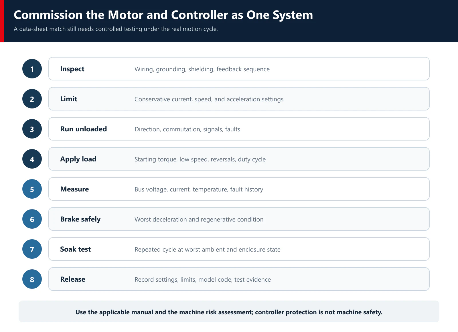
Record the firmware, parameters, motor wiring, controller model, test load, ambient condition, and acceptance results. Without that record, a later replacement unit or software change can silently alter the validated system.
Common BLDC Controller Selection Mistakes
Matching only motor and controller wattage
Power does not define starting current, acceleration current, speed margin, overload duration, or braking energy. Use the complete operating point.
Comparing two current numbers without their definitions
A motor's rated current and a controller's labeled current may refer to different locations and mathematical conventions. Confirm the definitions before using a greater-than comparison.
Assuming a 48 V motor only needs a 48 V controller
Check the complete voltage window, required loaded speed, controller voltage drop, supply sag, transients, and regenerative rise.
Treating PWM, Hall, FOC, and CAN as competing options
They describe different layers. PWM may be a command or switching method, Hall sensors provide position sectors, FOC is a current-control algorithm, and CAN is a communication interface.
Choosing sensorless control without testing the loaded start
Basic back-EMF sensorless control has the least position information at standstill and low speed. Test startup, handover, reverse movement, and restart under the real load.
Ignoring deceleration because the motor runs correctly
The drive can operate normally during acceleration and trip on overvoltage during stopping. Include the power supply and energy-absorption path in the selection.
Assuming a larger controller is automatically safer
The motor still needs appropriate current limits, protection thresholds, tuning, wiring, and thermal validation. An oversized power stage does not configure itself around the motor.
Treating protection functions as machine safety
Drive fault functions protect equipment within stated conditions. They do not by themselves establish a safe stop, safe torque removal, guarding, emergency-stop performance, or compliance for the complete machine.
Information to Send a BLDC Controller Supplier
For an initial motor-and-controller review, send:
- exact motor model, winding, data sheet, and connection diagram;
- minimum, nominal, and maximum DC supply voltage;
- rated current and peak current with their measurement definitions;
- continuous torque, peak torque, peak duration, and repetition rate;
- minimum, normal, and maximum speed;
- load inertia, acceleration/deceleration, starting load, reversals, and motion cycle;
- Hall, encoder, or sensorless requirement and available signal details;
- speed or torque control objective and required accuracy;
- analog, PWM, pulse, CAN, RS485, digital I/O, and PLC requirements;
- regenerative/braking requirement and whether the supply can absorb energy;
- mechanical holding brake and release sequence, if applicable;
- ambient temperature, enclosure, mounting, cooling, cable lengths, vibration, dust, and moisture;
- applicable machine standards, prototype quantity, and production timing.
If a current value is copied from a data sheet, include the row title and test conditions. “48 V, 750 W, 20 A” is not enough to identify a compatible controller.
Frequently Asked Questions
Can any BLDC controller run any BLDC motor?
No. The voltage window, continuous and peak current, phase configuration, commutation method, pole count, speed range, Hall or encoder interface, control mode, and thermal conditions must be compatible. Phase and Hall sequence also need to be commissioned correctly.
What is the difference between a BLDC motor driver and a BLDC motor controller?
Industrial suppliers often use both terms for a complete unit that commutates the motor, regulates speed or torque, switches phase current, and handles protection. In electronics design, “motor driver” may instead mean only the gate-driver or power-stage portion. Check the block diagram and function list rather than relying on the product name.
What current rating should a BLDC controller have?
It must cover the required continuous current under the real cooling and ambient conditions and the required transient current for the specified duration and repetition rate. Before comparing values, confirm whether the motor and controller ratings refer to bus current, phase-current RMS, phase-current peak, or a software limit.
Can a 48 V BLDC motor use a 48 V controller?
Possibly, but the two labels are not enough. Check the controller's minimum and maximum bus voltage, the supply's real voltage range, voltage needed for the required loaded speed, undervoltage behavior, transients, and voltage rise during regenerative deceleration.
Should I choose Hall sensors or a sensorless controller?
Choose from the starting and low-speed requirement. Hall feedback is often the practical starting point for loaded starts, reversing, and repeatable commutation near zero speed. Basic back-EMF sensorless control can suit loads with a controlled startup and adequate running speed. The exact controller algorithm and machine test decide the result.
Do I need an encoder if the motor already has Hall sensors?
Not always. Hall sensors may be sufficient for commutation and ordinary speed control. An encoder may be needed when the application requires finer speed information or position-related functions that the controller supports. Confirm the feedback interface and control function before adding it.
Does a BLDC controller need a braking resistor?
Only when the motion cycle can return more energy than the battery, power supply, bus capacitance, controller, and other loads can safely absorb. High inertia, fast deceleration, overhauling loads, and vertical motion deserve particular attention. Calculate and test the worst case using the selected controller's instructions.
Is FOC always better than six-step control?
No. FOC can improve torque smoothness and low-speed control when the motor data, sensing, rotor-angle information, and tuning are suitable. Six-step control may be the simpler and more appropriate choice when its startup, ripple, noise, speed regulation, and cost meet the machine requirement. Compare validated system performance at the actual operating points.
Request a Motor-and-Controller Review
Send TENCH the motor model, supply-voltage range, continuous and peak torque, speed range, motion cycle, current definitions, starting load, feedback, interface, braking requirement, installation conditions, and quantity. The motor, driver, power supply, gearbox, feedback, and load can then be reviewed as one system.
Technical References
- Texas Instruments, Brushless-DC Motor Driver Considerations and Selection Guide
- Microchip Technology, AN885: Brushless DC Motor Fundamentals
- Microchip Developer Help, Six-Step Sensorless BLDC Motor Commutation
- STMicroelectronics, Design Considerations for Brushless Direct Current Motor Control
- maxon, Selection Criteria for Motor Controllers
- maxon Support, Measures in Case of Energy Recovery and Overvoltage
- TENCH BLD Series Brushless DC Driver
- TENCH TCBLD Series Brushless DC Driver
- TENCH TC5BLD750-GU Brushless DC Gearmotor
About the Author and Reviewer
Verna Lyu prepares practical motor-selection and application content with input from the TENCH factory and engineering team.
Wen Liu, Engineer, reviewed the technical content of this article.

Leave a Reply