
How to Size a BLDC Gearmotor: Torque, Speed, Ratio, and Duty Cycle
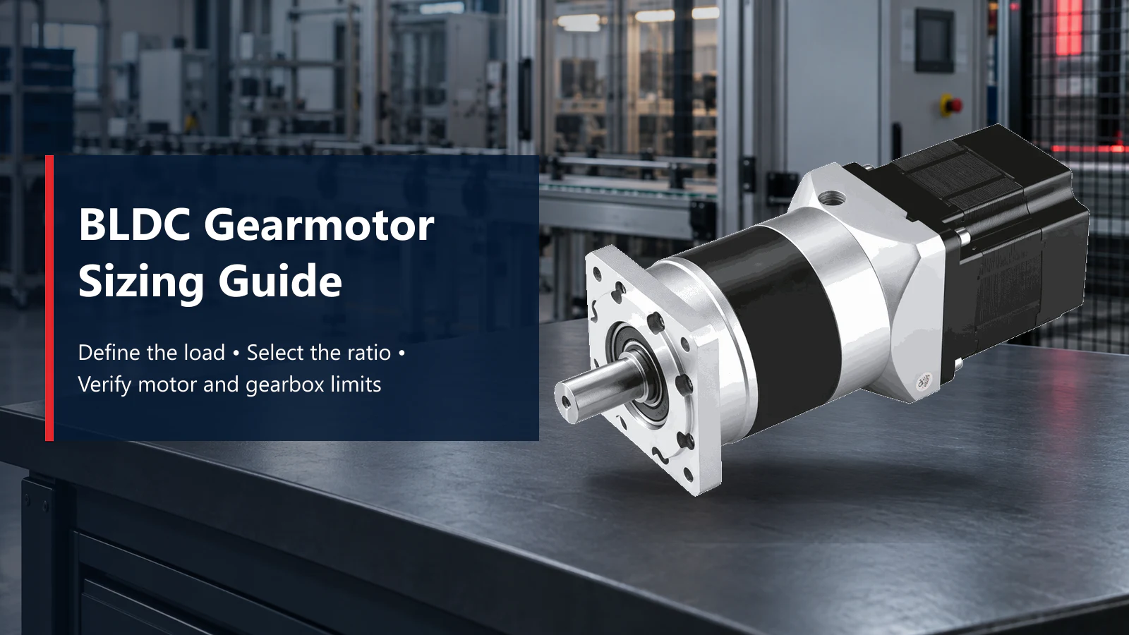
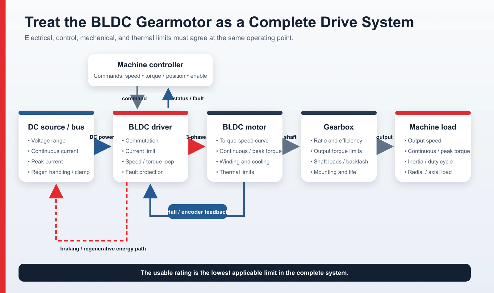
A BLDC gearmotor should be sized from the machine shaft back toward the motor. Start with the required output speed, continuous torque, peak torque, motion cycle, inertia, shaft loads, supply, and operating environment. Then select a practical gear ratio and check the motor, gearbox, driver, and thermal limits as one system.
A brushless motor with a gearbox can meet the target speed and torque only when every component is suitable for the same operating point. Motor wattage alone is not enough.
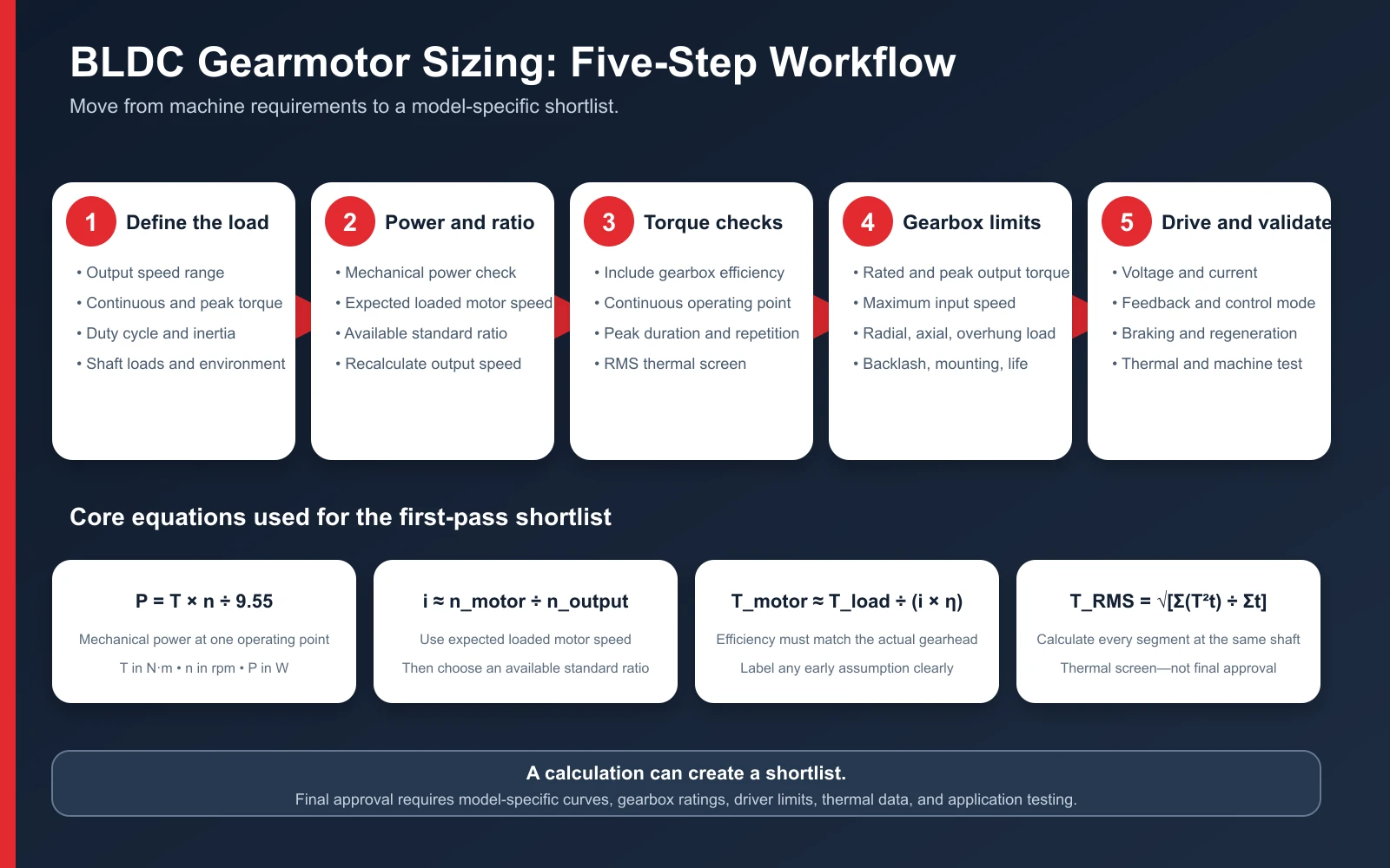
The process is easier to control when it is broken into five decisions:
- Define the load-side speed, torque profile, inertia, and mechanical loads.
- Estimate mechanical power and choose an initial ratio from the expected loaded motor speed.
- Compare continuous, peak, and RMS torque after allowing for gearbox efficiency.
- Examine the gearhead's torque, input-speed, shaft-load, backlash, lubrication, and mounting limits.
- Confirm the BLDC driver, power supply, feedback, braking, and protection requirements.
The result is a shortlist, not an approval. The final choice still depends on the torque-speed curves, thermal data, gearbox ratings, and application tests for the exact motor-and-gearbox combination.
Why BLDC Gearmotor Sizing Starts at the Load
Specify the torque and speed at the machine shaft before choosing motor power. Two applications can use the same mechanical power and still need different gearmotors. A continuously running conveyor may be limited by temperature rise, while an indexing mechanism may be limited by acceleration torque, repeated shock, or backlash. A vertical axis may also need a holding brake even when its running torque is modest. A wattage figure alone does not reveal which of these limits will govern the design.
The motor, gearbox, and drive can limit the system in different ways:
- A motor-limited system reaches the motor's continuous torque, peak torque, speed, current, or thermal limit first.
- A gearbox-limited system reaches the gearhead's allowable output torque, input speed, bearing load, backlash, or life limit first.
- A drive-limited system reaches the controller or power supply's current, voltage, regenerative-energy, or temperature limit first.
The usable gearmotor rating is the lowest applicable limit of the complete system.
1. Define the Output-Shaft Requirements
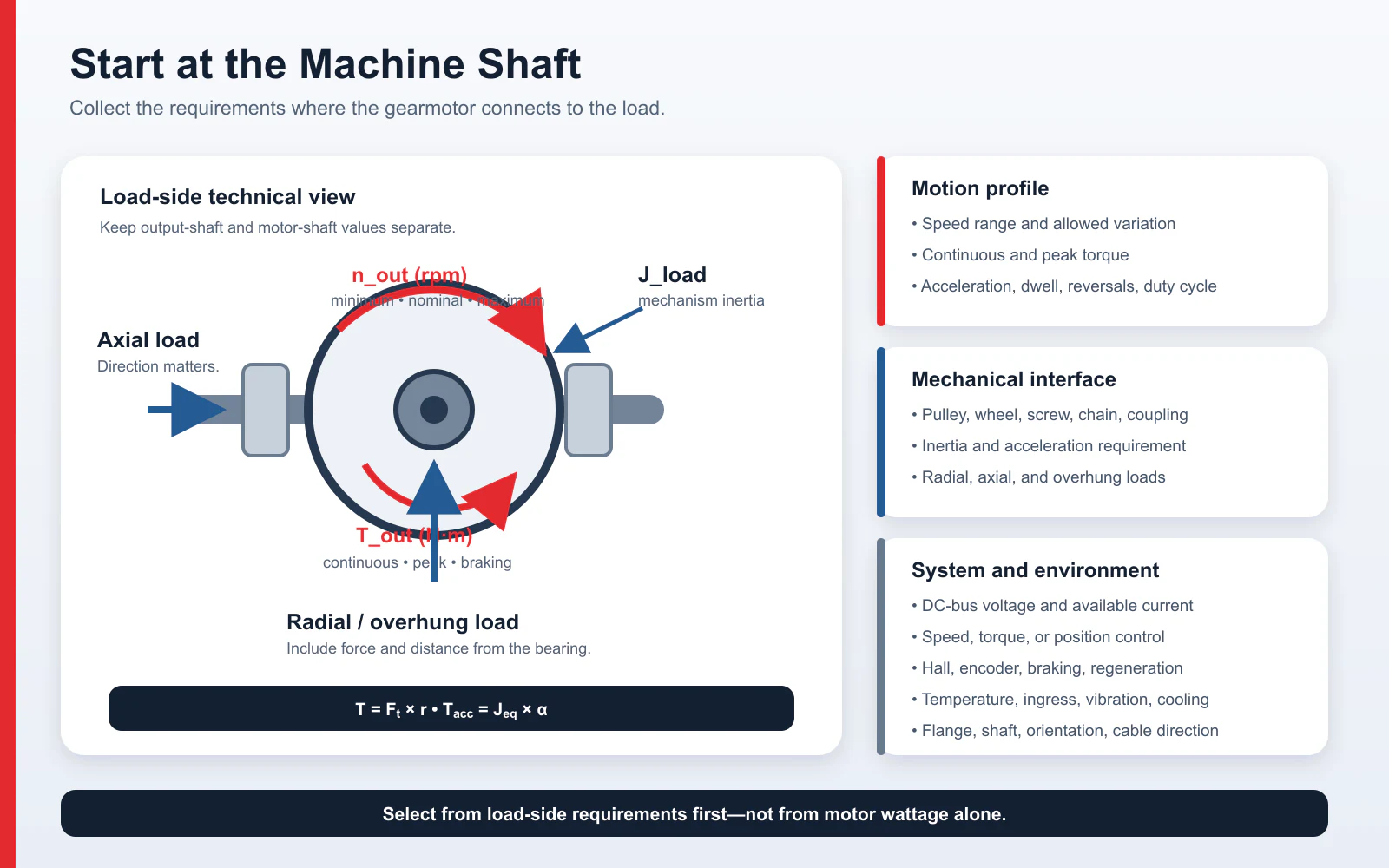
Record the requirements where the gearmotor connects to the machine. Keep motor-shaft and output-shaft values separate throughout the calculation.
| Required input | What to record | Why it matters |
|---|---|---|
| Output speed | Minimum, nominal, maximum, and allowed variation | Establishes the ratio and motor operating-speed range |
| Continuous torque | Load torque during the thermally dominant operating period | Screens the motor's continuous region and gearbox rated torque |
| Peak torque | Starting, acceleration, jam-clearing, shock, or braking torque | Screens motor peak torque, driver current, and gearbox overload capacity |
| Peak duration and frequency | Seconds per event and events per cycle or hour | A peak value without time is not a complete specification |
| Motion cycle | Acceleration, constant speed, deceleration, dwell, and reversals | Supports RMS torque and thermal evaluation |
| Inertia | Load, pulley, wheel, screw, coupling, and mechanism inertia | Determines acceleration torque and dynamic behavior |
| Radial, axial, and overhung load | Magnitude, direction, and distance from the output bearing | May determine the required shaft and gearhead bearing capacity before torque does |
| Power supply | Nominal, minimum, and maximum voltage; continuous and peak current | Constrains motor winding and driver selection |
| Environment | Ambient temperature, dust, water, vibration, altitude, and cooling | Affects thermal performance, sealing, lubrication, and life |
| Mechanical envelope | Flange, shaft, orientation, length, mass, and cable direction | Eliminates combinations that cannot be installed |
| Control objective | Speed, torque, or position; accuracy; communication; braking | Determines feedback and driver requirements |
For a conveyor or wheel, convert the required tangential force to shaft torque:
T = F × r
where T is torque in N·m, F is tangential force in N, and r is the pulley or wheel radius in m. If chains, belts, screws, or other components sit downstream of the gearmotor, include their efficiency, friction, and acceleration requirements in the load model.
Acceleration torque can be estimated from:
T_acc = J_eq × α
where J_eq is the equivalent inertia referred to the shaft being evaluated and α is angular acceleration. Combine friction, gravity, process force, and acceleration torque for each operating phase instead of hiding them inside one generic margin.
2. Calculate Power, Ratio, and Gearbox Efficiency
Mechanical power
At one operating point:
P (W) = T (N·m) × n (rpm) ÷ 9.55
An output shaft delivering 12 N·m at 140 rpm therefore provides approximately:
P = 12 × 140 ÷ 9.55 = 176 W
This is the mechanical power at the gearbox output. The motor must provide more mechanical power at the gearbox input because the transmission is not lossless.
Power is a useful cross-check, but it does not replace torque-speed data. A motor may have adequate rated power but insufficient torque at the required speed, or adequate peak torque but insufficient continuous thermal capacity. The load-first procedure in Oriental Motor's selection-calculation guide provides a useful independent reference for relating the drive mechanism, load torque, inertia, speed, and operating time.
Initial gear ratio and real output speed
For a reduction gearbox:
i ≈ n_motor ÷ n_output
and:
n_output,theoretical ≈ n_motor ÷ i
Use the expected motor speed under load, not the no-load speed or a headline maximum. If the motor is expected to run at 2,800 rpm and the machine needs approximately 140 rpm:
i = 2,800 ÷ 140 = 20
Choose a standard ratio that the manufacturer actually supplies, recalculate the operating point, and confirm that the driver can regulate the motor across the required speed range.
The reduction ratio itself remains fixed. However, the actual motor speed may fall below its nominal or rated value under load or because of controller and supply limits. Measured output speed can therefore be lower than the simple calculation based on nominal motor speed. For example, the TENCH TC5BLD300-PLE060 page notes that actual output speed may be approximately 2%–20% lower than the calculated value depending on load. A machine that needs tightly regulated speed should use closed-loop control and be verified at the real operating point.
Gearbox efficiency
Estimate output torque with:
T_output,estimated ≈ T_motor × i × η_gearbox
To work back from the load:
T_motor,required ≈ T_load ÷ (i × η_gearbox)
where η_gearbox is expressed as a decimal. Use 0.90 only if 90% efficiency is supported for the selected gearhead, ratio, speed, load, and operating condition—or label it clearly as an early calculation assumption.
There is no universal gearbox efficiency. It varies with gear type, number of stages, ratio, speed, load, lubricant, temperature, seals, and design. If a supplier publishes tested output torque for an integrated gearmotor, that model-specific rating is generally more useful than a value reconstructed from motor torque and a generic efficiency.
3. Check Continuous, Peak, and RMS Torque
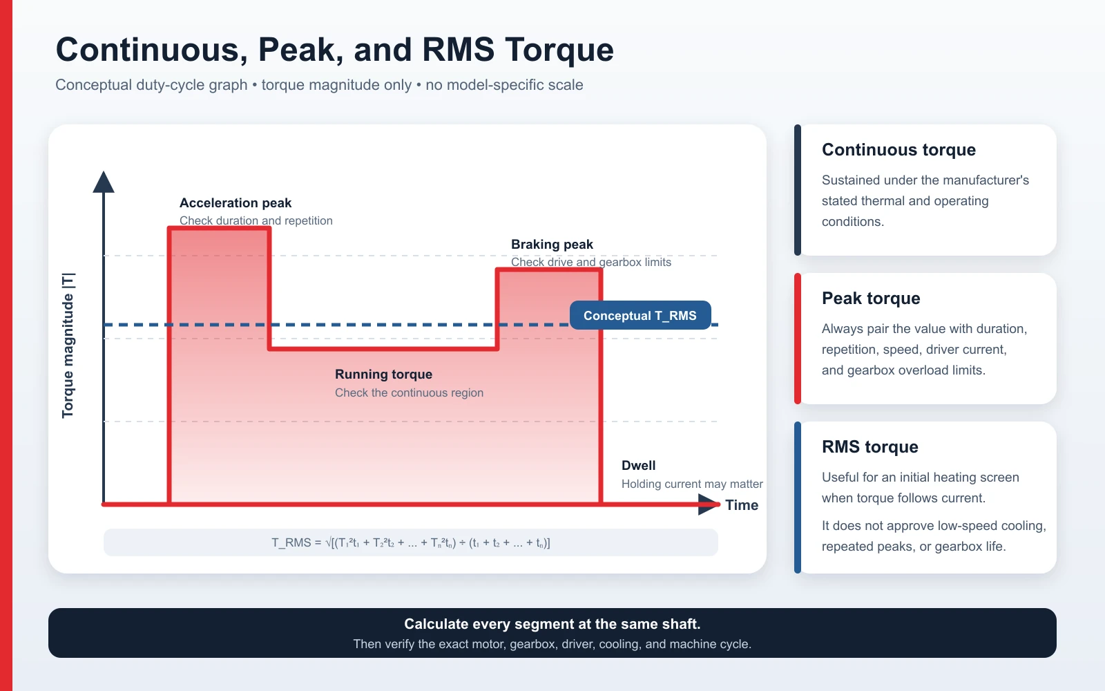
Continuous torque
The continuous operating point belongs inside the motor's continuous torque-speed region and below the gearbox's permitted continuous output torque. The driver also needs enough continuous current capacity for that point without overheating.
Do not compare a zero-speed or peak-torque value with a continuous running load. Torque capability can change with speed, winding, drive current, cooling, and control method.
Peak torque
A peak-torque value is useful only when its operating context is known. Record:
- peak duration and repetition rate
- motor speed during the event
- driver peak current and current-limit behavior
- power-supply voltage drop
- gearbox intermittent or emergency torque limit
- shaft, key, coupling, and driven-component limits
- braking or regenerative energy.
A motor's peak-torque rating does not establish how long that torque may be used, and it does not prove that the gearbox can transmit the multiplied value. Treat the motor and gearhead limits separately.
RMS torque for a variable cycle
For a multi-segment cycle, an initial torque-equivalent calculation is:
T_RMS = √[(T₁²t₁ + T₂²t₂ + ... + Tₙ²tₙ) ÷ (t₁ + t₂ + ... + tₙ)]
Calculate every segment at the same shaft. RMS torque is useful for screening copper-loss-related heating when torque is proportional to current, but it is not a complete thermal model. Low-speed cooling, dwell current, ambient temperature, mounting, repeated peaks, iron loss, driver switching, and gearbox heating still require model-specific data or testing.
4. Verify the Gearbox as a Separate Component
Once the ratio and torque calculation works, examine the gearhead on its own. Bodine Electric's gearmotor selection guide illustrates why duty, output torque, life, mounting, and gearbox rating remain separate application checks even when the motor calculation passes.
| Gearbox limit | What to verify |
|---|---|
| Rated output torque | Should exceed the required continuous load under the stated duty and conditions |
| Intermittent or emergency torque | Needs to cover the peak load for its actual duration and repetition |
| Maximum input speed | Needs to remain above the highest commanded motor speed |
| Radial and overhung load | Include sprocket, pulley, belt, chain force, and distance from the output bearing |
| Axial load | Include thrust from screws, helical components, or machine forces |
| Backlash and torsional stiffness | Should meet positioning, reversal, and settling requirements |
| Mounting and lubrication | Confirm orientation, lubricant, sealing, and temperature range |
| Shock and starts per hour | Repeated impact can determine gear and bearing life |
| Output shaft and key | Check bending, torsion, fit, coupling, and stress concentration |
| Noise and life targets | Compare values measured under defined test conditions |
If the calculated value T_motor × i × η exceeds the gearhead's mechanical rating, the gearbox—not the motor—sets the usable output.
5. Match the Driver, Power Supply, and Feedback
A standard three-phase BLDC motor needs compatible electronic commutation, so the motor and driver should be evaluated as one system:
- rated, minimum, and maximum DC-bus voltage
- continuous and peak current on a clearly defined phase-current or bus-current basis
- Hall sequence, encoder type, sensorless operating range, or other feedback
- speed, torque, or position-control mode
- acceleration and deceleration ramps
- current limit and stall protection
- dynamic braking, regenerative energy, brake resistor, or supply absorption
- overvoltage, undervoltage, temperature, and fault response
- PLC I/O, analog command, pulse/direction, or communication protocol
- cable length, grounding, shielding, and electromagnetic compatibility.
Hall sensors can support commutation and starting, but their resolution may not be sufficient for precise low-speed regulation or positioning. An encoder may be required for tighter speed control, accurate position, or repeatable low-speed motion. See How Does a BLDC Motor Work? for the underlying commutation and feedback principles.
Worked Example: A 300 W TENCH BLDC Planetary Gearmotor
This example shows how to build a preliminary shortlist. It is not an approved product selection.
Published motor data and calculation assumptions
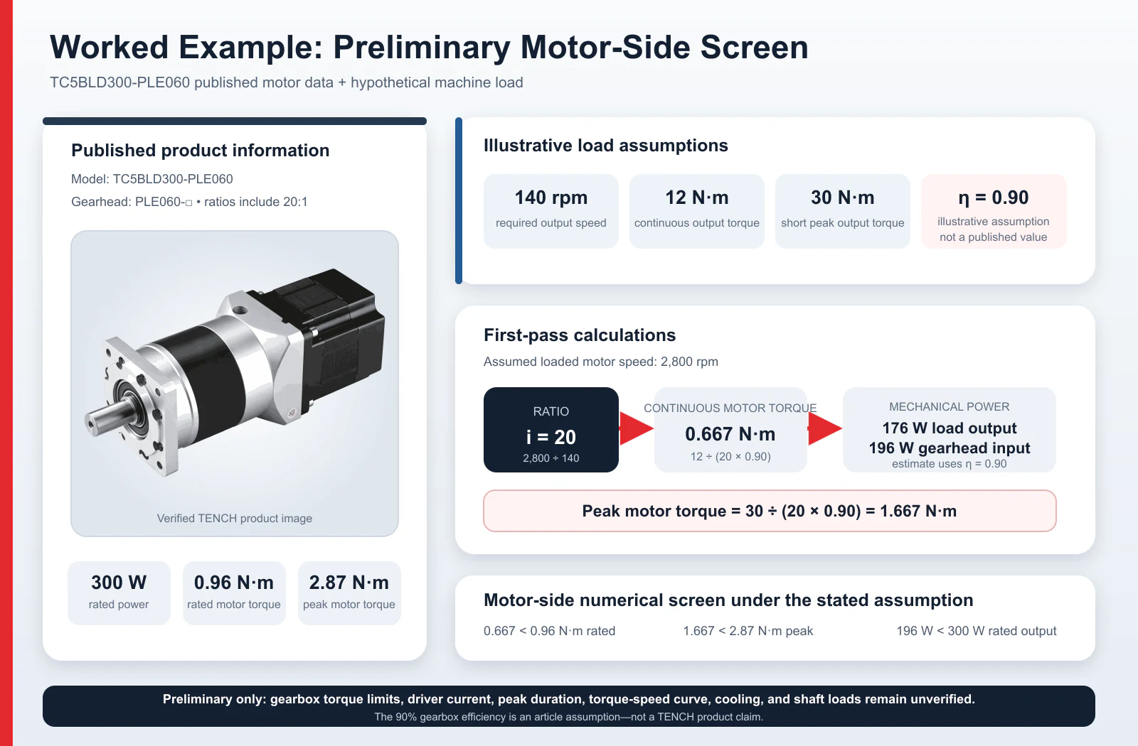
The TENCH TC5BLD300-PLE060 combines an 86 mm BLDC motor with a PLE060 precision planetary gearhead. The product page identifies the gearhead as PLE060-□; the box represents the selected reduction ratio rather than a separate motor model. Published data includes:
- rated power: 300 W
- rated motor speed: 3,000 rpm
- rated motor torque: 0.96 N·m
- peak motor torque: 2.87 N·m
- available reduction ratios including 20:1
- model-family winding options for 12, 24, 36, 48, and 310 V, each requiring a compatible drive.
Assume that a machine requires:
- output speed: approximately 140 rpm
- continuous output torque: 12 N·m
- short peak output torque: 30 N·m
- motor operating speed near 2,800 rpm
- illustrative gearbox efficiency: 90%.
The 90% value is an assumption for this example, not a published or guaranteed efficiency for the PLE060. Final calculations require the efficiency and torque ratings for the exact ratio, stage count, speed, load, lubricant, and temperature.
Ratio, continuous torque, and power
The initial ratio is:
i = 2,800 ÷ 140 = 20
A 20:1 ratio is listed for this product, so it passes the first availability check.
Required continuous motor torque:
T_motor,continuous = 12 ÷ (20 × 0.90) = 0.667 N·m
This is below the published motor rated torque of 0.96 N·m.
Output mechanical power:
P_output = 12 × 140 ÷ 9.55 = 176 W
Estimated gearbox-input mechanical power:
P_input ≈ 176 ÷ 0.90 = 196 W
Under the stated assumptions, the continuous torque and power calculations fall below the published motor-side ratings. The operating point still has to be checked against the model's torque-speed curve and actual cooling conditions.
Peak torque and the remaining limits
Required peak motor torque:
T_motor,peak = 30 ÷ (20 × 0.90) = 1.667 N·m
This is below the published motor peak torque of 2.87 N·m. If the 30 N·m peak occurs at 140 rpm, however, it represents approximately 440 W of mechanical output and cannot be treated as a continuous condition. Its duration, repetition, motor temperature, driver current, supply voltage, and the gearbox's peak rating all need approval.
| Check | Preliminary result | Evidence still required |
|---|---|---|
| Ratio availability | Pass: 20:1 is listed | Exact order code and gear stages |
| Continuous motor torque | Pass under the 90% efficiency assumption | Torque-speed curve and temperature rise |
| Continuous mechanical power | Pass under the 90% efficiency assumption | Loaded operating point and cooling |
| Motor peak torque | Numerically below the published peak | Permitted duration, repetition, and drive current |
| Gearbox continuous torque | Not verified | Rated output torque of the PLE060 gearhead at a 20:1 reduction ratio |
| Gearbox peak torque | Not verified | Allowed peak or emergency torque and duration |
| Output speed | 140 rpm when the motor runs at 2,800 rpm | Loaded motor speed and closed-loop regulation range |
| Shaft loads, backlash, and life | Not evaluated | Application geometry and PLE060 mechanical data |
| Driver and supply | Not evaluated | Voltage, current, braking, feedback, and protection data |
At this stage, the calculation supports a preliminary shortlist. Product approval begins with the missing gearbox, drive, thermal, and application data in the right-hand column.
Choosing the Gearbox Type
TENCH's Brushless DC Gear Motor range includes planetary, worm, right-angle, and other geared configurations. Select the architecture from the machine layout and performance requirements, then verify the exact product data.
| Gearbox type | Often considered when | Main checks |
|---|---|---|
| Planetary | Coaxial layout, compact torque density, dynamic motion, or controlled backlash is important | Stage count, ratio, efficiency, backlash, input speed, shaft loads, and noise |
| Parallel-shaft spur or helical | Straightforward reduction and cost-effective continuous rotation are priorities | Package length, gear stages, backlash, bearing load, noise, and lubrication |
| Worm | A compact 90-degree arrangement and high single-stage reduction are useful | Load-dependent efficiency, heat, wear, lubrication, backlash, and backdrivability |
| Bevel or hypoid right-angle | The shaft direction must turn 90 degrees but a worm set is not required | Efficiency, ratio range, backlash, offset, lubrication, noise, and backdrivability |
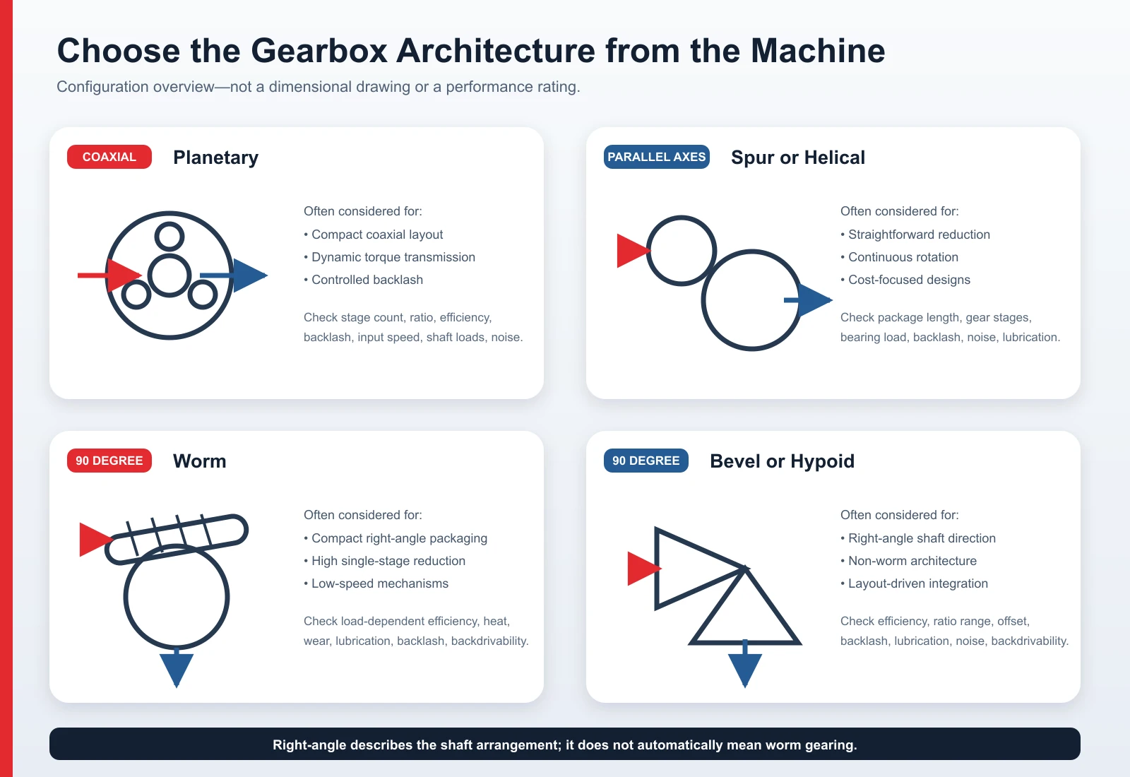
For a compact coaxial drive, a brushless DC planetary gear motor is often a practical candidate, but it is not automatically the best option for every machine. Packaging, accuracy, service life, cost, and shaft-load capacity can change the decision.
A worm gearbox must not be treated as a certified holding brake. Backdrivability depends on ratio, lead angle, friction, wear, lubrication, vibration, and load. Use a rated brake or another safety mechanism when loss of power must not allow motion.
For miniature mechanisms, TENCH also provides Micro Brushless DC Motors & Gearmotors. The same sizing method applies, although small geartrains can be particularly sensitive to shaft load, shock, thermal path, and the difference between intermittent and continuous torque.
Common Sizing Mistakes
- Selecting by wattage alone. Rated power is meaningful only with torque, speed, duty, and thermal conditions. Begin with the load-side torque-speed points.
- Using no-load speed for the final ratio. Use the expected controlled speed under load, then verify the real operating range.
- Multiplying peak motor torque by the ratio and calling it rated output torque. This ignores efficiency, peak duration, driver current, and the gearbox's mechanical limit.
- Applying one efficiency to every gearbox. An assumed value is acceptable for an early calculation only when it is identified and later replaced with model-specific data.
- Adding an arbitrary safety factor everywhere. Separate uncertainties such as shock, load estimation, temperature, starts, wear, and required life. Apply the manufacturer's service factor or design margin with its stated basis.
- Ignoring braking and regeneration. Decelerating a high-inertia load or lowering a vertical load can return energy to the DC bus. The drive and supply must absorb or dissipate it safely.
- Ignoring pulley or sprocket loads. The torque calculation may pass while the output shaft or bearing fails the overhung-load check.
- Treating a calculator result as approval. The final review must also cover backlash, bearing life, connector limits, cable routing, contamination, tuning, acoustic requirements, and temperature rise in the machine.
Information to Send a BLDC Gearmotor Supplier
Provide the following information in one request:
- application and driven mechanism
- required output speed range and regulation tolerance
- continuous output torque
- peak, starting, and braking torque, including duration and repetition
- full motion cycle, starts per hour, and duty cycle
- load and mechanism inertia
- pulley, sprocket, wheel, or screw dimensions
- radial, axial, and overhung load at the gearmotor shaft
- available DC voltage and continuous and peak current
- speed, torque, or position-control objective
- Hall, encoder, sensorless, PLC, and communication requirements
- braking, holding, and power-loss behavior
- flange, shaft, envelope, mounting orientation, and cable requirements
- ambient temperature, cooling, ingress, vibration, and altitude
- required life or maintenance interval under stated operating conditions
- prototype quantity, annual quantity, and project timing.
If the first decision is whether the machine should use a brushed or brushless motor, review Brushed vs Brushless DC Motors for Industrial Equipment before choosing the gearbox and control system.
Frequently Asked Questions
How do I calculate the gear ratio for a BLDC motor?
Divide the expected loaded motor speed by the required output speed: i ≈ n_motor ÷ n_output. Choose an available standard ratio, recalculate the operating point, and check loaded speed, gearbox efficiency, torque limits, and control range. Do not use no-load speed as the final design point.
Does a gearbox increase motor power?
No. A reduction gearbox decreases speed and increases torque while approximately conserving mechanical power before losses. Friction and other losses make the output mechanical power lower than the input mechanical power.
How much safety factor should I use for a BLDC gearmotor?
There is no universal percentage. The margin should reflect the known uncertainties and the manufacturer's service-factor method, including load estimation, shock, starts, temperature, duty, required life, gearbox type, and consequences of failure. Keep continuous, peak, and mechanical-limit checks separate.
What is the difference between continuous and peak torque?
Continuous torque can be sustained under the manufacturer's stated thermal and operating conditions. Peak torque is permitted only for a limited duration and repetition. The motor, driver, gearbox, shaft, coupling, and power supply must all tolerate the event.
Is a planetary gearbox always better than a worm or right-angle gearbox?
No. Planetary gearing is often used for a compact coaxial layout and dynamic torque transmission. A worm, bevel, or hypoid gearbox may suit a 90-degree layout. Efficiency, heat, backlash, backdrivability, shaft loads, lubrication, noise, cost, and mounting must be compared for the exact products.
What can a gear-ratio calculator tell you—and what can it not verify?
A calculator can screen ratio, speed, torque, and power. It cannot approve the final gearmotor because torque-speed curves, thermal limits, gearbox ratings, shaft loads, driver and power-supply compatibility, feedback, braking, environmental requirements, and validation in the machine still matter.
Request a BLDC Gearmotor Selection Review
Send TENCH the required output speed, continuous and peak torque, peak duration, duty cycle, supply, motion profile, shaft loads, dimensions, environment, feedback, and control requirements. TENCH can then review the motor, gearbox, driver, and feedback as one system. Submit your application details to TENCH.
Technical References
- ElectroCraft, Selecting a Brushless DC Motor or Gearmotor
- Bodine Electric, How to Select and Apply a Gearmotor
- Oriental Motor, Selection Calculations
- TENCH, TC5BLD300-PLE060 86 mm Brushless DC Planetary Gearmotor, 300 W

Leave a Reply