
How Does a BLDC Motor Work? Components, Commutation, Sensors, and Control
Author: Verna Lyu
Publication date: September 20, 2026
Technical reviewer: Wen Liu, Engineer — approved
Technical review date: September 20, 2026
Primary reader: OEM design engineers integrating BLDC motors into industrial equipment
Scope: Three-phase permanent-magnet BLDC motor systems used in industrial equipment
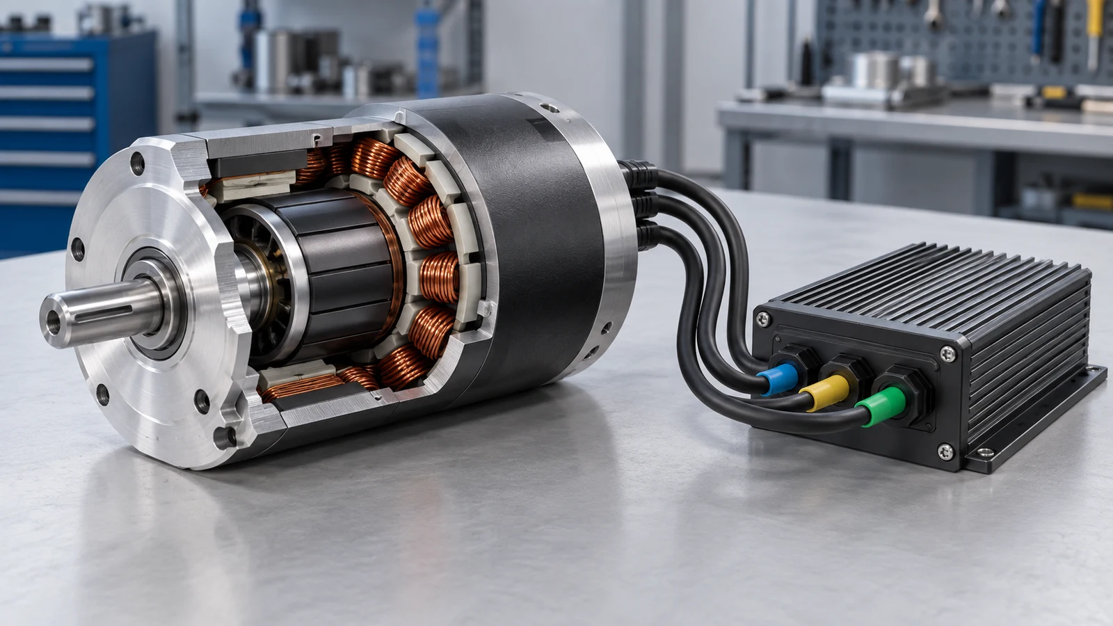
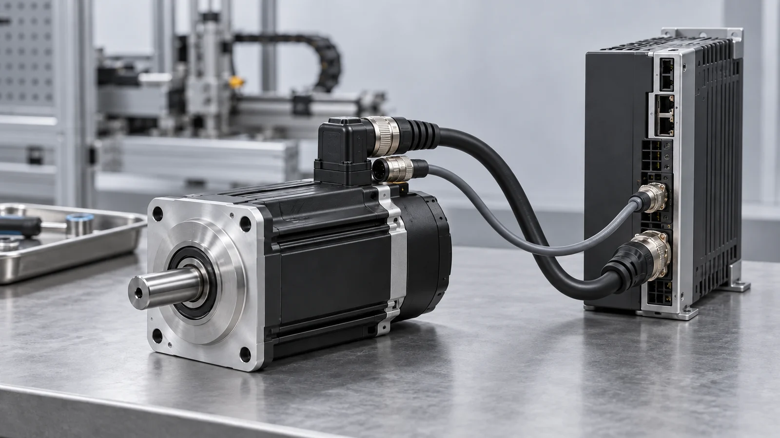
A brushless DC (BLDC) motor turns because an electronic controller energizes the stator phases in a sequence that keeps the stator magnetic field ahead of the permanent-magnet rotor. The controller needs rotor-position information from Hall sensors, an encoder, or a sensorless estimator. It then uses a three-phase inverter to switch current through the windings. The motor, controller, feedback method, power supply, load, and protection settings must therefore be selected as one system.
This guide is limited to three-phase permanent-magnet BLDC systems. It does not cover brushed DC, stepper, or induction motors. Model-specific voltage, current, torque, speed, thermal, feedback, and controller limits must still be confirmed from the relevant specifications and validated in the actual machine.
Key Takeaways
- A standard three-phase BLDC motor without integrated electronics does not commutate itself. A compatible controller and power stage are required.
- In six-step commutation, each electrical revolution is divided into six 60-degree sectors. Two phases are driven while the third is normally left floating.
- Hall sensors provide discrete rotor-position information at standstill and low speed. Basic back-EMF sensorless control needs sufficient rotor speed before the signal becomes reliable.
- PWM regulates phase voltage or current, but PWM is not the same as commutation.
- Six-step control is comparatively simple. Field-oriented control (FOC) can reduce torque ripple and improve low-speed control when correctly implemented, but it usually requires more detailed current and rotor-angle information, computation, and tuning.
- “BLDC,” “PMSM,” “sensored,” and “sensorless” are not complete selection specifications. The motor winding, back-EMF shape, pole count, controller algorithm, load, speed range, and thermal limits must be compatible.
Contents
- What parts make a BLDC system work?
- What happens during rotation?
- How does six-step commutation work?
- Hall sensors, encoders, or sensorless estimation?
- What does the controller actually do?
- Six-step control or FOC?
- What is the difference between BLDC and PMSM?
- How should an industrial BLDC system be selected?
- Common technical mistakes
- Information to send a motor supplier
- Frequently asked questions
What Parts Make a BLDC System Work?
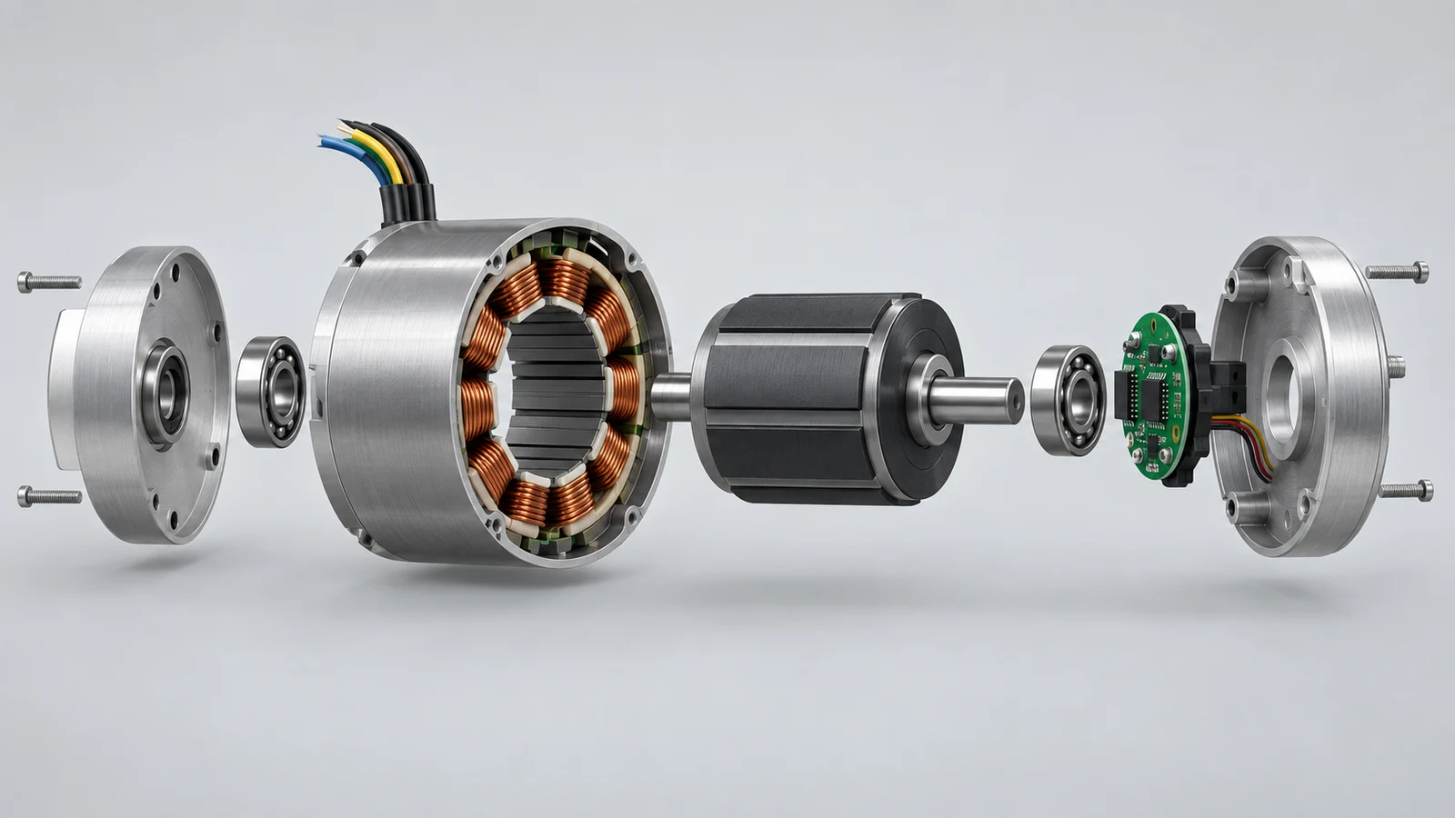
A working BLDC installation contains more than the motor. At minimum, it needs a permanent-magnet rotor, a wound stator, a three-phase power stage, control logic, a rotor-position source, and electrical and thermal protection.
| Part | Function | Integration check |
|---|---|---|
| Permanent-magnet rotor | Produces the rotor magnetic field | Pole count, magnet temperature limit, inertia, maximum speed |
| Wound stator | Produces the rotating magnetic field when its phases are energized | Winding connection, resistance, inductance, voltage, current, thermal path |
| Bearings and shaft | Support the rotor and transmit mechanical output | Radial and axial load, mounting, speed, lubrication, service life |
| Position source | Tells the controller where the rotor is, directly or by estimation | Hall sequence, encoder format, alignment, signal voltage, sensorless operating range |
| Three-phase inverter | Switches DC-bus power into the motor phases | Bus voltage, continuous and peak current, switching devices, heat dissipation |
| Control and protection | Determines commutation, PWM, speed or torque loops, and fault response | Algorithm, current limit, overvoltage, undervoltage, temperature, stall behavior |
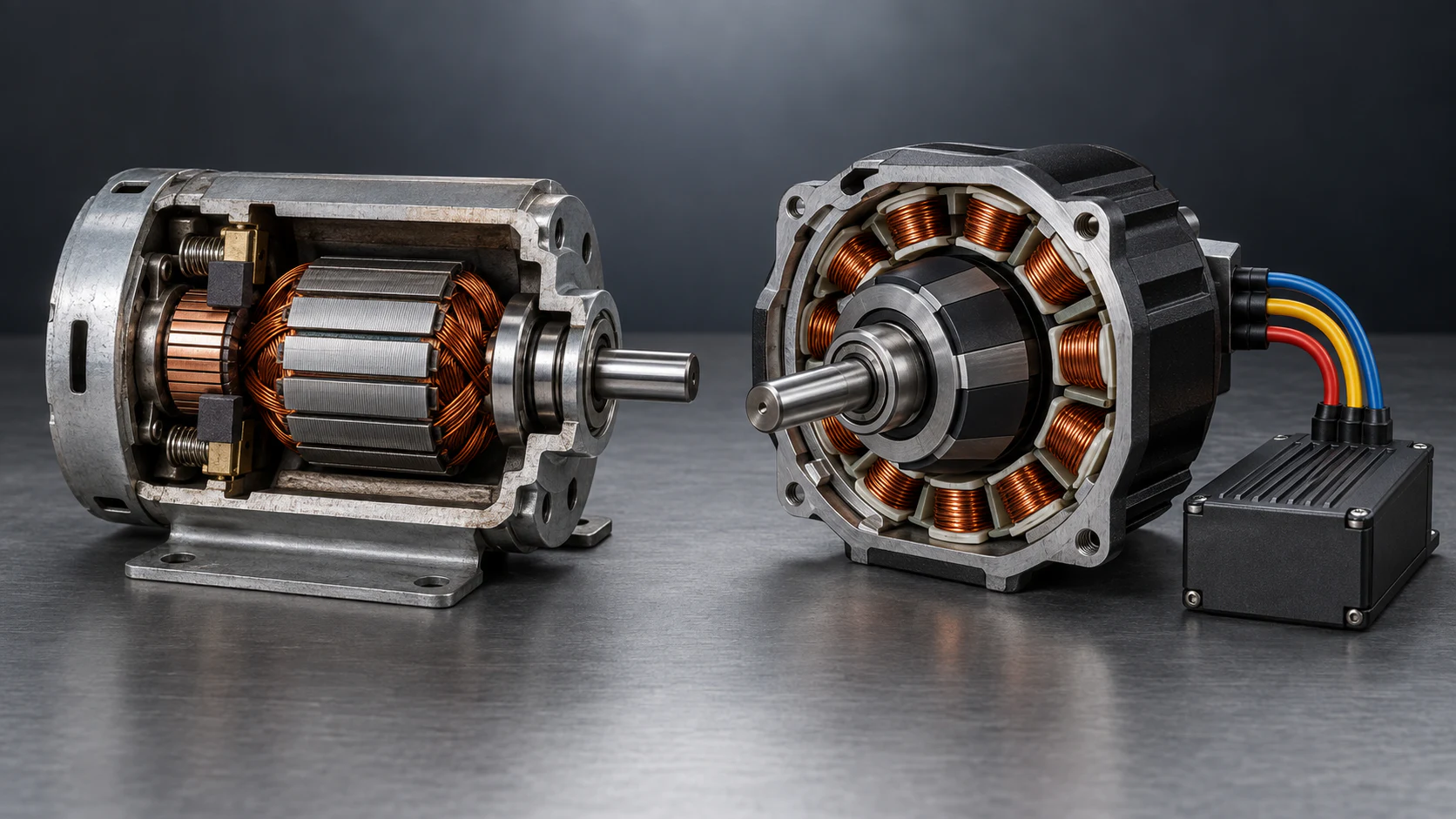
The stator is fixed to the housing, so winding heat can be conducted toward the frame. The rotor carries permanent magnets and turns with the shaft. Removing the brush-and-commutator interface eliminates brush wear and brush arcing, but it does not eliminate bearing wear, winding temperature limits, controller losses, or maintenance elsewhere in the machine.
What Happens During Rotation?
The controller repeats five functions while the motor runs:
- It obtains or estimates rotor position.
- It selects the phase-current state that should produce torque in the commanded direction.
- The inverter switches the motor phases according to that state.
- Stator current produces a magnetic field that interacts with the rotor magnets.
- The controller advances to the next state as the rotor moves.
This sequence is synchronized in electrical angle, not directly in mechanical shaft angle. If a motor has p pole pairs, one mechanical revolution contains p electrical revolutions:
Electrical frequency (Hz) = pole pairs × mechanical speed (rpm) ÷ 60
For example, a motor with four pole pairs running at 3,000 rpm has an electrical frequency of:
4 × 3,000 ÷ 60 = 200 Hz
This 200 Hz value is the electrical cycle frequency. It is not the controller's PWM switching frequency, which is normally much higher and must be selected with the power stage, acoustic targets, motor inductance, losses, and electromagnetic-compatibility requirements in mind.
How Does Six-Step Commutation Work?
Six-step commutation divides each electrical revolution into six sectors of 60 electrical degrees. In a common 120-degree conduction scheme, one phase connects toward the positive DC bus, a second phase connects toward the negative bus, and the third phase is not actively driven. The controller changes the active pair at each sector boundary.
| Step | High-side phase | Low-side phase | Floating phase |
|---|---|---|---|
| 1 | A+ | B− | C |
| 2 | A+ | C− | B |
| 3 | B+ | C− | A |
| 4 | B+ | A− | C |
| 5 | C+ | A− | B |
| 6 | C+ | B− | A |
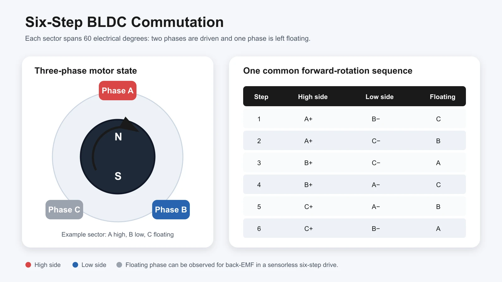
In a Hall-sensored drive, the Hall-state changes can be used to select the next commutation sector. In a basic sensorless six-step drive, the controller monitors the back electromotive force, or back-EMF, of the floating phase. A detected zero crossing provides a timing reference; the next commutation is scheduled according to the control method and the required phase delay.
Back-EMF is proportional to speed. At standstill and very low speed, a basic back-EMF zero-crossing method does not have a strong enough signal for dependable position detection. The controller must use a suitable starting method before transferring to closed-loop sensorless commutation. The acceptable startup method depends on load torque, inertia, allowed reverse movement, required starting time, and controller design.
Hall Sensors, Encoders, or Sensorless Estimation?
The right feedback method depends on what the machine must do near zero speed, during startup, and under changing load.
| Position method | Information available | Standstill and low speed | Main advantages | Integration risks |
|---|---|---|---|---|
| Hall sensors | Discrete rotor sectors | Available | Robust commutation reference, practical startup, moderate wiring | Hall order and electrical alignment must match the controller; resolution is limited |
| Incremental or absolute encoder | Higher-resolution position and speed | Available, depending on encoder type and homing method | Precise speed or position control; useful for servo behavior | Added cost, wiring, alignment, interface, and environmental requirements |
| Basic back-EMF sensorless | Zero crossings or phase-voltage information | Weak or unavailable at standstill | Removes rotor sensors and their wiring; useful when startup conditions are controlled | Open-loop startup, filtering, switching noise, minimum reliable speed, load sensitivity |
| Model-based sensorless estimator | Estimated rotor angle from measured electrical behavior | Capability depends on algorithm and motor data | Can support smoother control without a mechanical sensor | Requires suitable motor parameters, current/voltage measurement, computation, and tuning |
“Sensorless” does not mean “without feedback.” It means there is no dedicated mechanical rotor-position sensor. The controller still uses measured voltage, current, back-EMF, or a motor model to estimate the information it needs.
What Does the Controller Actually Do?
An industrial BLDC controller or drive normally combines four functions:
- Power conversion: a three-phase bridge switches the DC supply into the motor phases.
- Commutation or vector control: the algorithm determines which switches operate and when.
- Closed-loop regulation: speed, current, torque, or position commands are compared with feedback.
- Protection and supervision: current, voltage, temperature, stall, and other fault conditions are monitored according to the controller design.
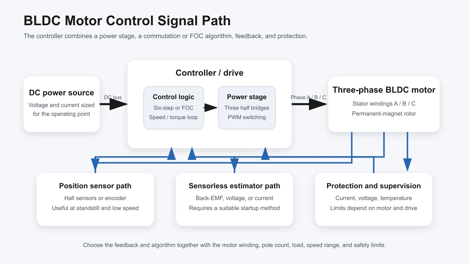
PWM changes the on-time of the inverter switches within each switching period. It can regulate average phase voltage or current, but it does not by itself determine the correct commutation sector. The controller still needs rotor-position information and a commutation or FOC algorithm.
The term electronic speed controller (ESC) is common in drones, model vehicles, and some traction products. Industrial equipment more often uses motor controller or drive because the unit may also control current, torque, direction, braking, acceleration, communication, alarms, and protection. The name alone does not confirm that a controller is compatible with a particular motor.
Six-Step Control or FOC?
Both six-step control and field-oriented control can operate a three-phase permanent-magnet motor, but they control the phase currents differently.
| Decision factor | Six-step or trapezoidal control | Field-oriented control |
|---|---|---|
| Basic method | Switches among six discrete voltage states | Regulates current components in a rotating reference frame |
| Typical implementation | Hall-sensored or back-EMF sensorless | Sensored or sensorless rotor-angle feedback plus phase-current measurement |
| Low-speed smoothness | Commutation torque ripple may be more noticeable | Can provide smoother torque when correctly tuned |
| Computation and sensing | Comparatively simple | Higher computation, sensing, parameter, and tuning requirements |
| Best starting point | Cost-sensitive speed control with acceptable ripple | Precision speed, torque, acoustic, or dynamic requirements |
| Main caution | Startup and low-speed behavior must be validated | Poor parameters, sensing, or tuning can cancel the expected benefit |
FOC is not automatically the most efficient choice at every speed and load. Actual system efficiency depends on the motor winding, magnetic design, inverter devices, switching strategy, controller tuning, mechanical load, speed, cooling, and operating point. Compare motor-and-drive test data at the required duty cycle rather than selecting from the algorithm name alone.
What Is the Difference Between BLDC and PMSM?
Within the three-phase scope of this guide, BLDC and permanent-magnet synchronous motor (PMSM) are both terms used for permanent-magnet synchronous machines. In common engineering usage, BLDC often refers to a motor designed for trapezoidal back-EMF and six-step commutation, while PMSM often refers to a motor designed for more sinusoidal excitation and vector control.
The boundary is not always strict in product naming. Some motors marketed as BLDC can be operated with sinusoidal control or FOC, and some controllers support multiple algorithms. Compatibility must be confirmed from the motor's winding data, back-EMF waveform, pole count, sensor configuration, current and voltage limits, and the controller manufacturer's guidance.
How Should an Industrial BLDC System Be Selected?
Start with the machine requirement, not the motor label:
- Define continuous torque, peak torque, speed range, acceleration, inertia, and duty cycle at the motor shaft.
- Confirm whether the machine must start under load and whether any reverse movement is acceptable during startup.
- Define speed, torque, or position accuracy, including behavior at zero and low speed.
- Set the available DC voltage, continuous current, peak current, regeneration or braking requirements, and power-supply limits.
- Check installation space, shaft load, gearbox, mounting, ambient temperature, cooling, ingress protection, vibration, and cable length.
- Select the motor winding, controller, feedback, communication, and protection settings as a compatible set.
- Validate temperature rise, starting behavior, fault response, acoustic noise, and electromagnetic compatibility in the actual machine.
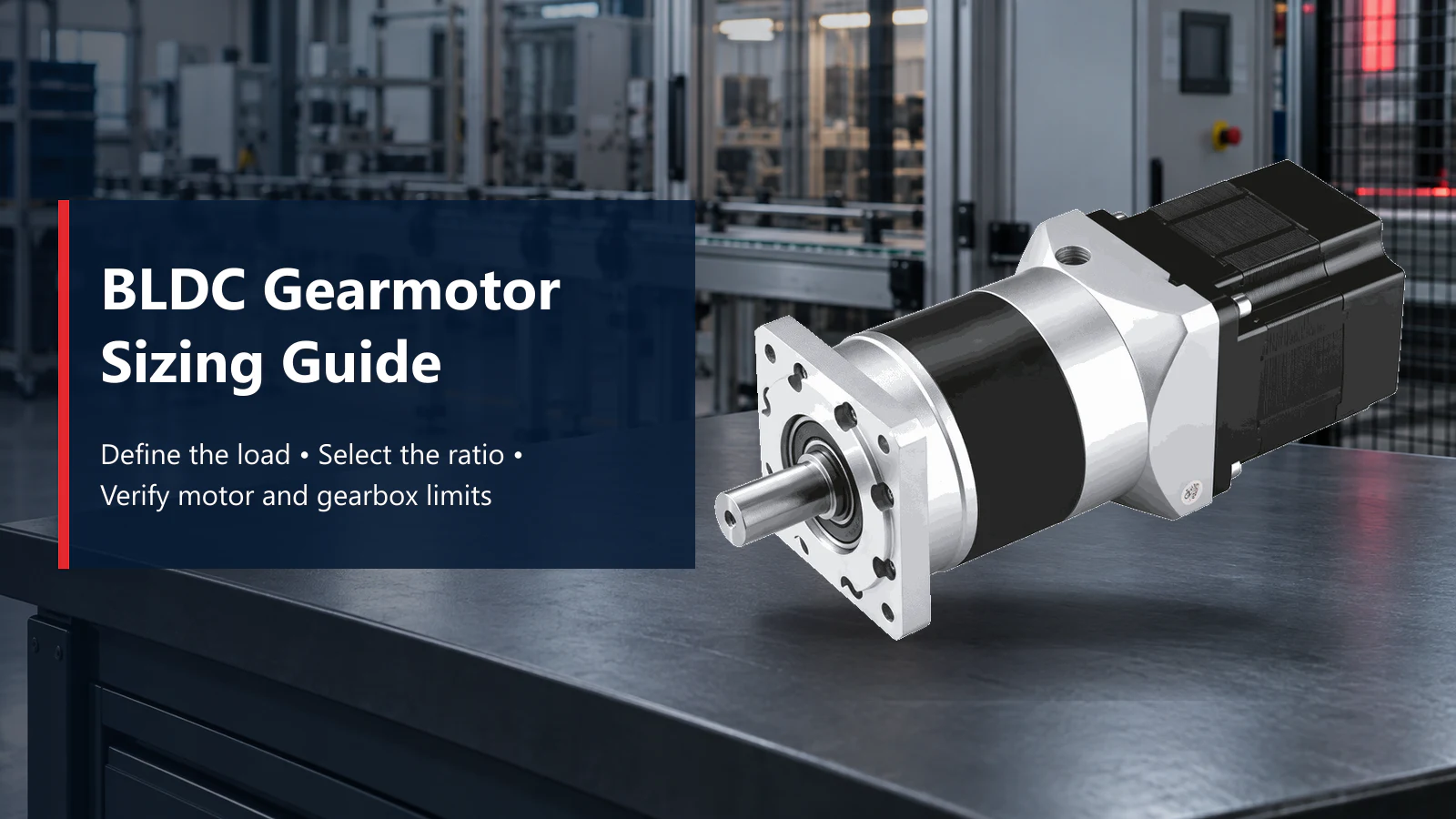
TENCH publishes separate ranges for micro brushless DC motors and gearmotors and high-power brushless DC motors. The required controller, feedback, and gearbox must still be confirmed for the selected model and operating point.
The Anjian Medical Equipment project provides an application context for brushless motors in an intelligent robotic arm. It should not be used as proof that the same motor or controller fits another machine without reviewing that machine's load, motion profile, installation, and safety requirements.
If the first decision is whether to use a brushed or brushless motor, read Brushed vs Brushless DC Motors for Industrial Equipment before selecting the feedback and control method.
Common Technical Mistakes
The most costly errors come from treating the motor, controller, feedback method, and load as independent items. The following claims should be rejected unless the selected motor-and-drive combination has been checked under the required operating conditions.
Treating a BLDC Motor as a Two-Wire Motor
A standard three-phase BLDC motor cannot be operated correctly by connecting it directly to a DC supply. It needs a compatible controller for electronic commutation. Integrated-drive motors are an exception only because the commutation electronics are already built into the product.
Assuming Hall Sensors Always Improve Efficiency
Hall sensors provide rotor-position information; they do not guarantee higher efficiency. Efficiency depends on the complete electromagnetic and power-electronic design and the operating point.
Assuming Sensorless Control Is Suitable for Every Startup
Basic back-EMF sensing is weakest at standstill. A high-inertia or loaded mechanism may need Hall sensors, an encoder, a more advanced estimator, or a specifically validated startup routine.
Calling a Brushless System Maintenance-Free
Removing brushes reduces one maintenance item. Bearings, seals, gearboxes, connectors, cooling surfaces, cables, and the controller can still require inspection or replacement.
Assuming Brushless Operation Eliminates EMI
Removing brush arcing can reduce one source of electrical noise, but PWM edges, cable current, grounding, shielding, and layout can still create conducted or radiated interference.
Publishing a Universal Service-Life Number
There is no responsible single-hour life claim for all BLDC motors. Bearing load and speed, winding temperature, insulation, magnet temperature, vibration, contamination, starts and stops, controller settings, and gearbox conditions can all affect life.
Information to Send a Motor Supplier
For an initial motor-and-controller review, provide:
- supply voltage and available current;
- continuous torque, peak torque, and peak duration;
- target, minimum, and maximum speed;
- duty cycle and motion profile;
- load inertia, acceleration, starting load, and stopping requirement;
- speed, torque, or position accuracy;
- Hall, encoder, sensorless, communication, and PLC requirements;
- shaft, flange, envelope, gearbox, brake, and cable requirements;
- ambient temperature, cooling, ingress, vibration, and installation orientation;
- estimated quantity and prototype schedule.
Motor power alone is not enough. Torque and speed must be stated at the same operating point, and both continuous and short-duration peak conditions should be identified.
Frequently Asked Questions
Can a BLDC motor run without a controller?
No—not as a standard three-phase motor with no built-in electronics. Its stator phases must be electronically commutated by a compatible controller and power stage. A product sold as an integrated-drive BLDC motor can accept a simpler external command only because its commutation electronics are already inside the assembly. Always check the wiring and controller requirements for the exact model.
Can a sensorless BLDC motor start from zero speed?
Yes, but only when the controller has a startup method suited to the motor and load. Basic back-EMF detection cannot determine rotor position at standstill, so the controller must first align or accelerate the rotor by another method. Startup torque, inertia, allowed reverse movement, current limit, and the handover speed to closed-loop sensorless operation must all be validated.
Are three Hall sensors always required?
No. Three digital Hall sensors are common in six-step BLDC systems because they identify six rotor-position sectors, but they are not universal. Other systems may use an encoder, resolver, model-based estimator, back-EMF detection, or a different sensor arrangement. The signal voltage, sequence, electrical alignment, connector, and controller input requirements must match the selected motor.
Is FOC always better than six-step control?
No. FOC can provide smoother torque, better low-speed behavior, or improved dynamic control when the motor model, current measurement, rotor-angle information, and tuning are suitable. It is not automatically more efficient at every operating point. Six-step control may be the better engineering choice when its startup behavior, torque ripple, speed regulation, acoustic performance, and cost already meet the machine requirement.
How long does a BLDC motor last?
There is no universal service-life value for all BLDC motors. Life depends on bearing load and speed, winding and magnet temperature, duty cycle, starts and stops, vibration, contamination, controller settings, cooling, gearbox conditions, and maintenance. Use model-specific life or reliability data only with its stated test conditions, then validate the motor in the actual load and environment.
Request a Motor-System Review
Send TENCH the voltage, torque-speed points, duty cycle, startup load, control objective, feedback requirement, installation dimensions, environment, and estimated quantity. The motor, controller, gearbox, and feedback method can then be reviewed as one system. Submit your application details to TENCH.
Technical References
- Microchip Technology, AN885: Brushless DC Motor Fundamentals
- Microchip Developer Help, Introduction to BLDC Motor Commutation and Control Architectures
- Microchip Developer Help, Six-Step Sensorless BLDC Motor Commutation
- Microchip Technology, AN1160: Sensorless BLDC Control with Back-EMF Filtering Using a Majority Function
- STMicroelectronics, PMSM and BLDC Motor Control
About the Author and Reviewer
Verna Lyu prepares practical motor-selection and application content with input from the TENCH factory and engineering team.
Wen Liu, Engineer, reviewed and approved the current technical content on September 20, 2026.

Leave a Reply