
How Does a Servo Motor Work? Components, Control Loops, and Selection
Author: Verna Lyu
Technical reviewer: Wen Liu, Engineer — approved
Technical review date: September 21, 2026
Publication status: Published September 21, 2026
Primary reader: OEM design engineers selecting a servo system for an industrial machine
Scope: Rotary industrial servo systems; model-specific ratings and machine-safety validation remain outside this article
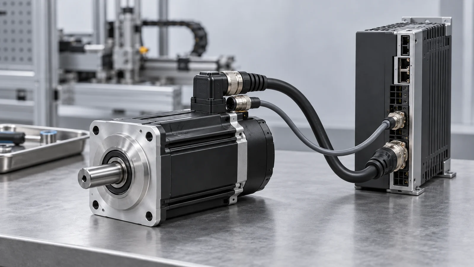
A servo motor system controls torque, speed, or position by comparing a command with measured motion and correcting the error in real time. The complete axis normally includes a motor, servo drive, feedback device, motion controller, power supply, cables, and mechanical transmission. Selection therefore cannot be based on motor power alone. An OEM engineer must define the motion profile, calculate peak and root-mean-square (RMS) torque, check speed against the motor’s speed–torque curve, reflect load inertia through any gearing, and confirm feedback, voltage, braking, environmental, and safety requirements. This guide explains that workflow for rotary industrial servo systems. It does not replace the motor and drive manuals, machine risk assessment, or application testing.
Key Takeaways
- A servo is a closed-loop motion system, not one universal motor construction.
- The drive compares a command with feedback and regulates current or torque, velocity, and, when required, position.
- Motor-mounted feedback does not measure backlash, compliance, or pitch error elsewhere in the machine. A load-side encoder may be required when the actual load position must be controlled directly.
- Peak torque must cover acceleration and disturbances; RMS torque must remain within the continuous thermal capability for the complete duty cycle.
- Encoder resolution is not the same as final machine accuracy. Mechanics, feedback location, tuning, stiffness, backlash, thermal growth, and control architecture all matter.
- The motor, drive, feedback protocol, power supply, brake, cables, gearbox, controller, and safety functions must be confirmed as a compatible system.
Contents
- What is a servo motor system?
- How does closed-loop servo control work?
- Which components must be matched?
- How do servo motors differ from stepper and basic BLDC systems?
- What determines the correct servo size?
- A practical servo selection workflow
- Where are servo systems a good fit?
- Common servo selection and commissioning mistakes
- What information should you send a servo supplier?
- Frequently asked questions
- Request a servo-system review
What Is a Servo Motor System?
A servo system is a feedback-controlled actuator that makes a mechanical axis follow a torque, speed, or position command. In industrial equipment, the word servo usually describes the way the axis is controlled rather than one winding or rotor type.
The motor may be a permanent-magnet synchronous motor, a brushless DC motor, a brushed DC motor, a direct-drive motor, or another machine designed for closed-loop control. Modern industrial rotary servos are commonly brushless permanent-magnet motors, but the label alone does not establish the voltage, commutation method, feedback interface, torque capability, or drive compatibility.
A complete servo axis typically contains:
- a motion controller or PLC that creates the command;
- a servo drive that closes one or more control loops and switches power;
- a motor that converts electrical power into torque;
- an encoder, resolver, or other feedback device;
- the coupling, gearbox, belt, screw, rack, or other transmission;
- the driven load; and
- protection, braking, cables, grounding, and safety functions.
This system definition is important. Replacing only the motor with a unit of similar wattage does not prove that the feedback, torque–speed curve, connector pinout, drive algorithm, inertia, brake, or thermal behavior will match.
How Does Closed-Loop Servo Control Work?
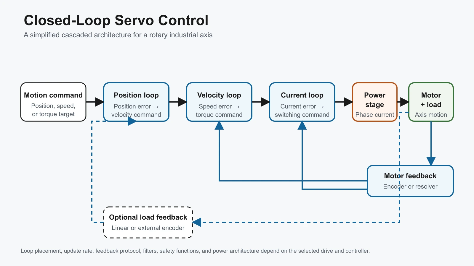
The controller sends a target to the drive. The feedback device reports actual motion. The drive calculates the difference, applies the control algorithm, and changes motor current through the power stage. This cycle repeats rapidly so the axis can reject disturbances and follow the commanded motion within the system’s limits.
Why Are Current, Velocity, and Position Loops Nested?
Industrial servo drives commonly use cascaded loops. The inner current loop responds first and controls torque-producing current, which is closely related to torque for a permanent-magnet servo motor within its operating range. The velocity loop commands the current loop. The position loop, when used, commands the velocity loop.
| Control loop | Main comparison | Typical output to the next inner function | Engineering concern |
|---|---|---|---|
| Current or torque loop | Commanded current versus measured current | Power-stage switching command | Current measurement, motor constants, drive current limits, switching and thermal limits |
| Velocity loop | Commanded speed versus estimated or measured speed | Torque or current command | Load inertia, friction, stiffness, resonances, filters and gain |
| Position loop | Commanded position versus measured position | Velocity command | Feedback location, following error, backlash, compliance and trajectory |
Not every application uses all three loops in the same place. The drive may close all loops, or a motion controller may close an outer position loop while the drive controls velocity and current. Schneider Electric documents current, velocity, and position loops as a cascade in its servo-drive control architecture, while OMRON notes that the drive, motion controller, or both may process the loops depending on the application.
Motor Feedback Versus Load Feedback
An encoder mounted on the motor shaft measures motor motion. This is often called a semi-closed or motor-feedback system. It can provide excellent motor control, but it cannot directly observe gearbox backlash, belt stretch, screw pitch error, coupling compliance, or movement between the motor and the load.
When the actual table, arm, or load position must be measured, a linear scale or external rotary encoder can close an additional load-side position loop. That can improve load-position accuracy, but it also introduces another feedback path and may expose mechanical compliance or resonances that require careful design and tuning. A higher encoder count at the motor does not by itself remove mechanical error.
Which Components Must Be Matched?
The safest selection method is to treat every electrical and mechanical interface as part of one compatibility review.
| Component | What it does | What must be confirmed |
|---|---|---|
| Servo motor | Produces torque and motion | Rated and peak torque, speed–torque curve, inertia, voltage, current, thermal limits, shaft and mounting |
| Servo drive | Regulates the motor and switches power | Motor support, feedback protocol, continuous and peak current, DC bus, control modes, communication and protection |
| Feedback device | Reports motor or load motion | Incremental or absolute type, resolution, multi-turn behavior, supply, interface, alignment and cable length |
| Motion controller or PLC | Creates trajectories and coordinates axes | Command interface, update rate, synchronization, homing, limits and machine sequence |
| Power and braking system | Supplies and absorbs electrical energy | Input voltage, peak demand, regeneration, braking resistor or common bus, fusing and disconnects |
| Mechanical transmission | Converts motor motion to load motion | Ratio, efficiency, backlash, torsional stiffness, allowable speed, reflected inertia and service factors |
| Cables and grounding | Carry power, feedback and communication | Connector pinout, shielding, routing, bend life, electromagnetic compatibility and flex rating |
| Brake and safety functions | Hold or stop the axis under defined conditions | Brake purpose, voltage, release timing, vertical-load behavior, safe torque off and machine risk assessment |
In a typical industrial servo axis, the motor main-circuit cable and the encoder-feedback cable are separate assemblies connected to different drive ports. Some systems integrate brake conductors into the motor cable or use different connector formats, but the selected manuals determine the pinout, shielding, grounding, routing, and permitted cable length. Do not infer wiring from connector shape or cable color alone.
A holding brake should not automatically be treated as a dynamic service brake. Its permitted stopping duty, emergency role, release timing, and wear limits must be checked in the selected product documentation.
How Do Servo Motors Differ from Stepper and Basic BLDC Systems?
The categories overlap, so the comparison must be based on the complete control architecture rather than the motor name alone. A brushless permanent-magnet motor can be used in a servo system when the drive, feedback, and control functions support the required closed-loop performance. Closed-loop stepper systems also exist.
| Decision factor | Industrial servo system | Typical open-loop stepper system | Basic BLDC speed-control system |
|---|---|---|---|
| Primary strength | Dynamic torque, speed, or position regulation with feedback | Simple commanded incremental motion without continuous position correction | Electronic commutation and regulated rotation speed |
| Feedback | Normally motor feedback; optional load feedback | Usually none, although closed-loop stepper products exist | Hall sensors or sensorless estimation may support commutation; an encoder may be optional |
| Position control | Integrated or coordinated through the drive/controller | Position inferred from commanded steps if synchronism is maintained | Not guaranteed by the BLDC label; depends on controller and feedback |
| Tuning | Required to match load inertia, stiffness and dynamics | Usually limited for open-loop operation | Depends on control mode; basic speed control may require less tuning |
| Best fit | Axes with demanding motion profiles, disturbance rejection, coordinated motion, or monitored following error | Cost-sensitive point-to-point motion within verified torque and speed margin | Fans, pumps, rollers, conveyors, or other speed-controlled loads when precise axis positioning is not required |
This table is a starting point, not a universal ranking. The correct choice depends on required speed, acceleration, settling time, load variation, holding behavior, mechanical stiffness, acceptable fault response, integration effort, and cost.
If the earlier decision is whether to use a brushed or brushless motor, see Brushed vs Brushless DC Motors for Industrial Equipment. For electronic commutation and BLDC control in more detail, see How Does a BLDC Motor Work?.
What Determines the Correct Servo Size?
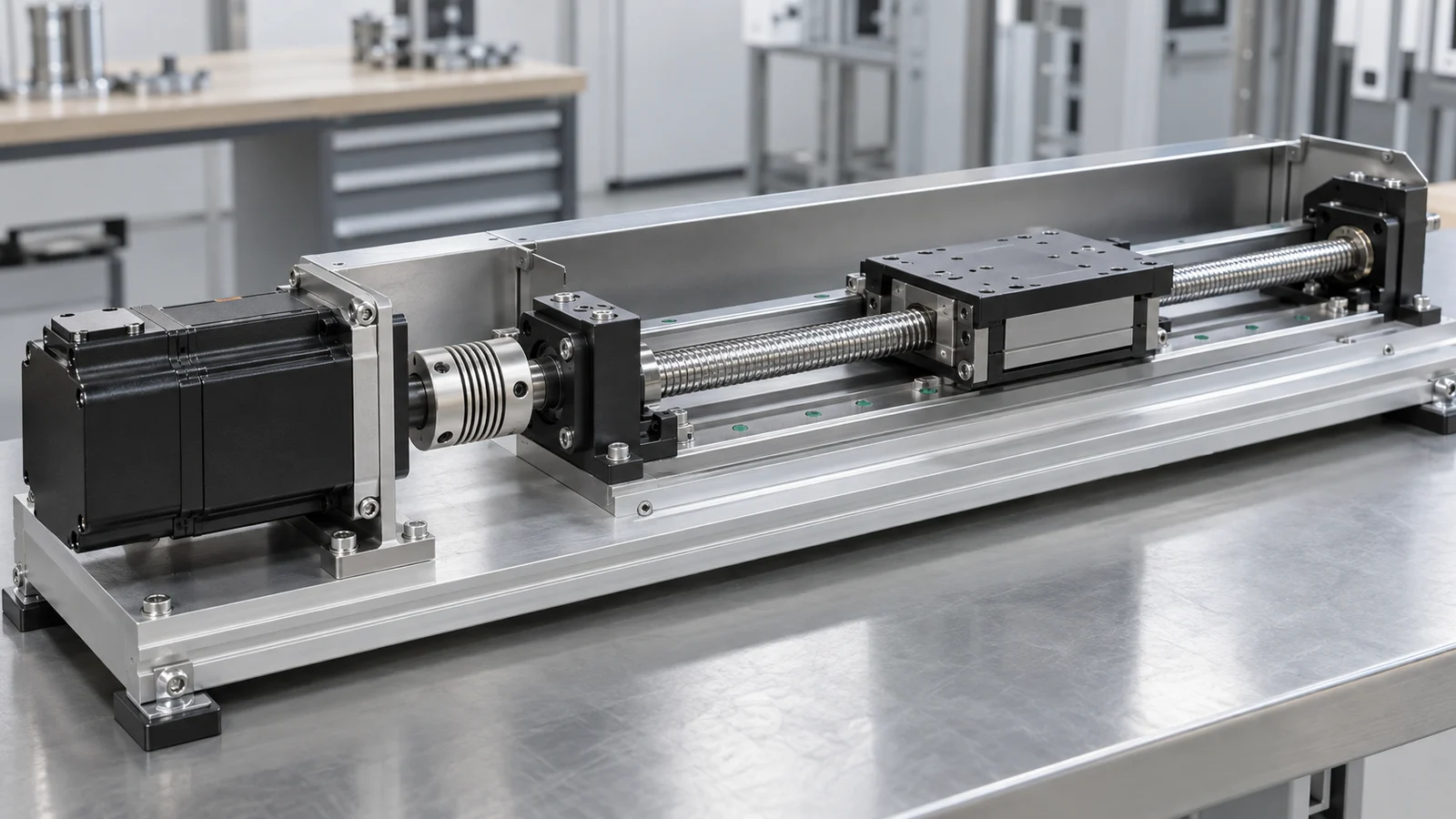
Servo sizing starts with the machine’s motion profile, not a target wattage. Yaskawa identifies speed, maximum torque at speed, RMS torque at speed, and inertia ratio as core sizing factors. Secondary checks include voltage, feedback, environment, space, cost, regeneration, and transmission design.
Define the Complete Motion Profile
For each segment of one repeatable cycle, record:
- distance or angle;
- move time;
- acceleration and deceleration time;
- dwell time;
- direction;
- external force or torque;
- friction and transmission efficiency;
- moving mass or inertia; and
- expected disturbances or process force.
The fastest segment determines required speed. Acceleration, gravity, process force, and friction contribute to torque. A vertical axis also needs a controlled strategy for gravity, brake release, stopping, and power loss.
Check Peak Torque at the Required Speed
Peak torque occurs during acceleration, deceleration, impact, or process-force events. Calculate it from the load and motion profile, add relevant friction and external forces, then check the required torque at the actual motor speed against the manufacturer’s intermittent region and permitted duration.
Peak torque is not a continuous rating. The drive must also supply the required peak current, and the power supply and DC bus must tolerate the event. Repetition rate and thermal state matter.
Calculate RMS Torque for Thermal Loading
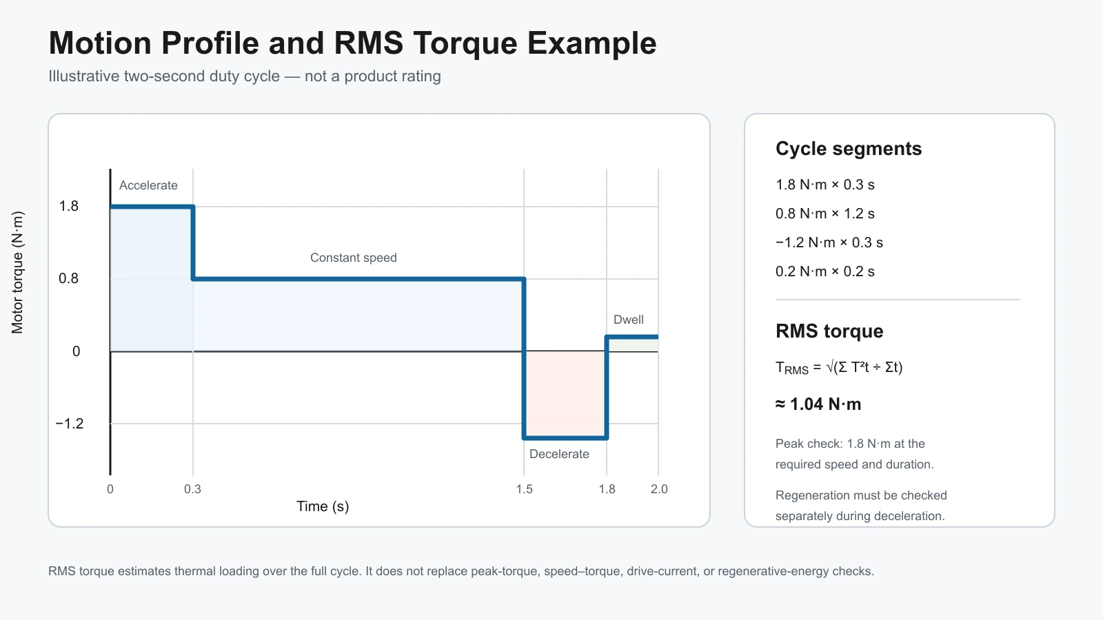
For a cycle divided into segments, RMS torque can be estimated as:
TRMS = √[(T₁²t₁ + T₂²t₂ + … + Tₙ²tₙ) ÷ (t₁ + t₂ + … + tₙ)]
where T is motor torque in N·m and t is segment time in seconds. This is a thermal sizing calculation; it does not replace the peak-torque or speed check.
Consider a two-second example cycle:
| Segment | Torque | Time |
|---|---|---|
| Accelerate | 1.8 N·m | 0.3 s |
| Constant speed | 0.8 N·m | 1.2 s |
| Decelerate | −1.2 N·m | 0.3 s |
| Dwell or hold | 0.2 N·m | 0.2 s |
The calculated RMS torque is:
TRMS = √[(1.8²×0.3 + 0.8²×1.2 + 1.2²×0.3 + 0.2²×0.2) ÷ 2.0] ≈ 1.04 N·m
The sign of deceleration torque disappears when squared, but regeneration and braking must still be checked separately. The example axis therefore needs at least 1.8 N·m of permitted peak torque at the relevant speed and a continuous thermal capability above 1.04 N·m under the stated installation and ambient conditions.
Reflect Load Inertia Through the Transmission
For an ideal ratio N = motor speed ÷ load speed, load inertia reflected to the motor is approximately:
Jreflected = Jload ÷ N²
If the load inertia is 0.004 kg·m² and the motor turns five revolutions for one load revolution, the ideal reflected load inertia is:
0.004 ÷ 5² = 0.00016 kg·m²
If the chosen motor inertia is 0.00004 kg·m², the idealized reflected-load-to-motor inertia ratio is 4:1. The real calculation must also include the coupling, gearbox, screw, pulley, motor rotor, and other moving components, and it must account for transmission efficiency where appropriate.
There is no universal requirement that every servo axis use a 1:1 inertia ratio. A lower ratio generally makes high dynamic performance and tuning easier, but allowable values depend on the drive, motor, mechanism, move profile, stiffness, control bandwidth, and performance target. Use the selected manufacturer’s sizing guidance rather than a single rule of thumb.
Verify Speed, Voltage, Drive Current, and Regeneration
The required operating points must lie within the motor’s continuous or intermittent speed–torque envelope as applicable. Confirm rated speed, maximum speed, field-weakening behavior if supported, continuous current, peak current, DC-bus or supply voltage, and motor back-EMF compatibility.
During deceleration or lowering of an overhauling load, mechanical energy can return to the DC bus. The drive may need a braking resistor, regenerative unit, shared DC bus, or a longer deceleration time. Do not assume that a resistor included in a drive can absorb every machine cycle.
Select Feedback from the Accuracy Requirement
Choose the feedback type only after defining what must be measured:
- An incremental encoder reports changes in position and normally requires a reference procedure to establish machine position after power-up.
- A single-turn absolute encoder retains the angular position within one revolution.
- A multi-turn absolute encoder can also retain revolution count, subject to its operating principle and system configuration.
- A resolver can be suitable where robustness is more important than very high digital resolution.
- A load-side encoder or linear scale measures the mechanism closer to the controlled point.
Final accuracy must be budgeted across encoder quantization, interpolation, mounting alignment, backlash, compliance, screw or gear error, thermal growth, controller update, filtering, and tuning. Resolution should never be published as finished-axis accuracy without that analysis.
A Practical Servo Selection Workflow
Use the following sequence so that the selected motor does not become the starting assumption.
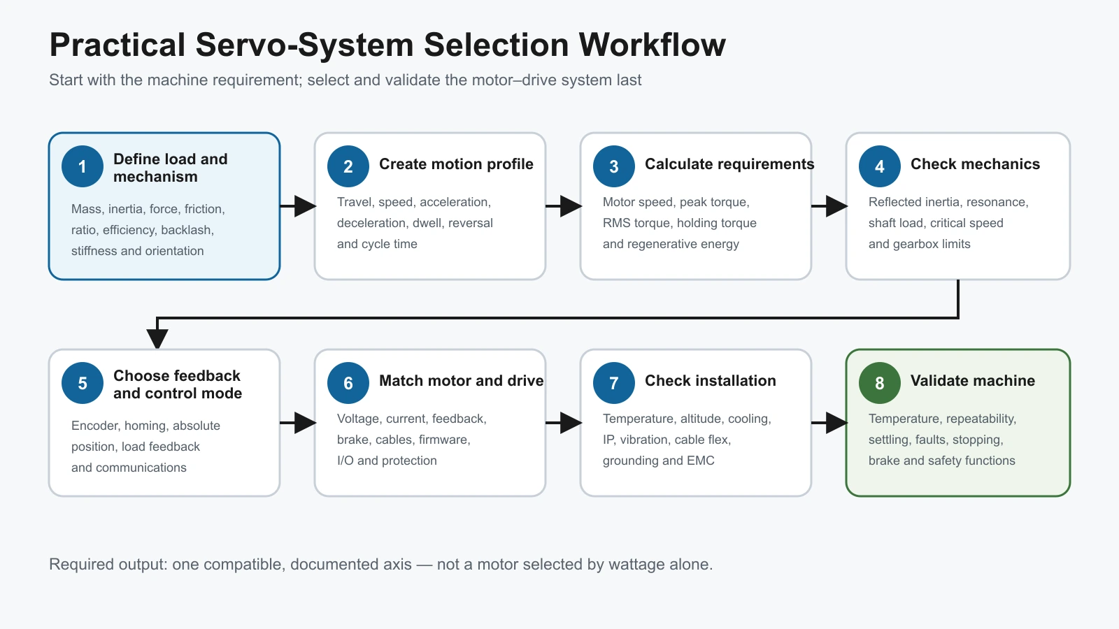
- Define the load and mechanism. Record mass, inertia, external force, friction, transmission type, ratio, efficiency, backlash, stiffness, shaft loads, and installation orientation.
- Create the motion profile. State travel, maximum speed, acceleration, deceleration, dwell, cycle time, reversal, stopping, and process force.
- Calculate speed and torque. Determine motor speed, peak torque at speed, RMS torque, holding torque, and regeneration for the complete cycle.
- Check inertia and mechanics. Reflect load inertia, include transmission components, verify critical speed, torsional resonance, bearing loads, and gearbox limits.
- Choose feedback and control mode. Define torque, velocity, position, homing, absolute-position, load-feedback, synchronization, and communication requirements.
- Match motor and drive. Confirm voltage, current, feedback protocol, motor data, brake, cables, connectors, firmware support, I/O, network, and protection.
- Check installation and environment. Confirm ambient temperature, altitude, cooling, enclosure, ingress protection, vibration, contamination, cable flexing, grounding, and electromagnetic compatibility.
- Validate the machine. Test temperature rise, peak events, repeatability, settling, resonance, stopping, brake behavior, fault response, and safety functions under representative conditions.
TENCH lists a DC Servo Motor & Controller product category for project review. The category page should be used as a starting point; the exact motor, drive, feedback, and mechanical requirements still need to be matched to the application.
Where Are Servo Systems a Good Fit?
Servo systems are most valuable when the machine needs controlled acceleration, high-speed torque, disturbance correction, coordinated axes, monitored following error, or repeatable positioning over a demanding motion profile.
Typical mechanisms include ball screws, indexing tables, robot joints, pick-and-place axes, packaging feed axes, cutting or printing registration, tension control, and automated handling. The industry name alone does not prove suitability. A medical or robotic mechanism, for example, may add safety, noise, cleanliness, validation, or regulatory requirements beyond normal motor sizing.
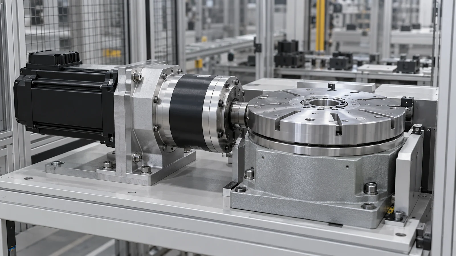
TENCH’s Anjian Medical Equipment project provides a public example of a brushless motor used in an intelligent robotic-arm context. It is application context only, not proof that the same motor, feedback, drive, or safety architecture fits another machine.
Common Servo Selection and Commissioning Mistakes
Selecting by Power Alone
Two motors with the same rated power can have different rotor inertia, rated speed, peak torque, continuous torque, winding voltage, encoder, thermal behavior, and physical envelope. Check the required operating points and complete axis, not the wattage label.
Treating Peak Torque as Continuous Torque
Peak torque is limited by drive current, motor magnetic and thermal limits, speed, and permitted duration. Repeated peak events raise RMS torque and may overload the motor or drive even when each event is brief.
Equating Encoder Resolution with Machine Accuracy
High feedback resolution can improve control information, but it cannot remove mechanical backlash, compliance, pitch error, or thermal movement. Feedback location determines which errors the loop can observe.
Using a Universal Inertia-Ratio Rule
An inertia ratio is a design and tuning input, not a pass/fail number that applies to every axis. Verify it against the selected motor–drive system, motion profile, mechanical stiffness, bandwidth, and settling requirement.
Tuning Around a Mechanical Problem
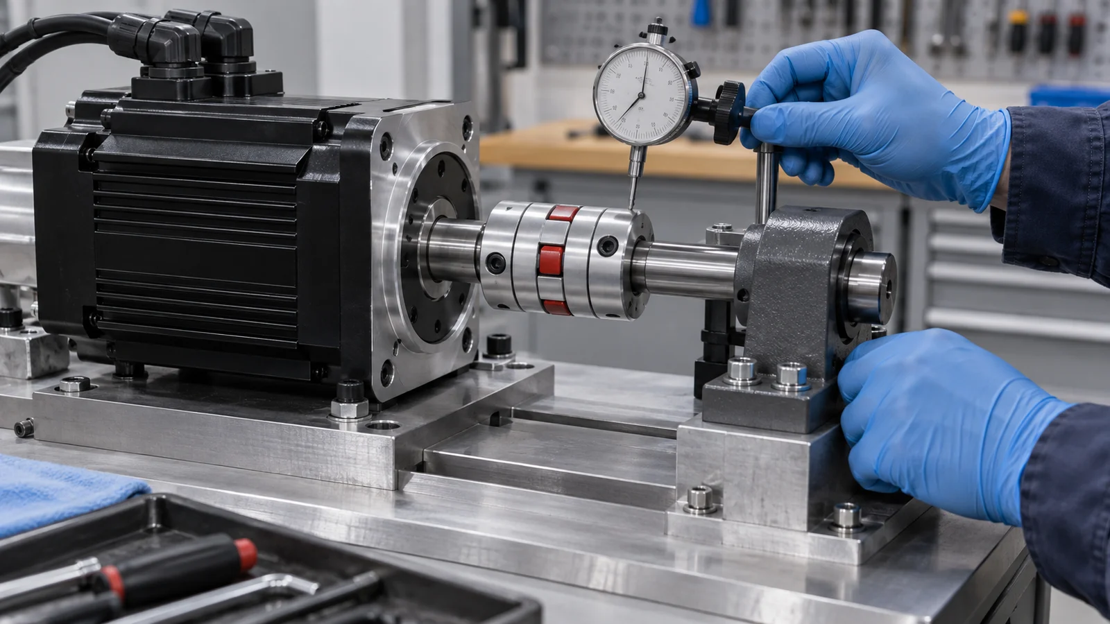
Loose couplings, backlash, flexible frames, resonance, poor alignment, damaged bearings, or unsuitable gearboxes cannot always be corrected with higher gains or filters. Inspect the mechanics before increasing control aggressiveness.
Ignoring Regeneration and Vertical-Axis Risk
Fast deceleration and gravity-driven loads can return energy to the bus. Confirm braking hardware, overvoltage behavior, stopping sequence, holding brake, and safe response to power loss.
What Information Should You Send a Servo Supplier?
For a useful first review, send one complete axis requirement rather than a preferred motor wattage:
- mechanism drawing and transmission type;
- moving mass and calculated load inertia;
- travel or rotation per cycle;
- maximum speed and motor-side speed;
- acceleration, deceleration, dwell, and total cycle time;
- continuous, peak, friction, gravity, and process torque or force;
- required positioning accuracy, repeatability, settling time, and feedback location;
- available supply voltage and controller or PLC interface;
- communication network, I/O, homing, brake, and absolute-position requirements;
- mounting, shaft, cable, connector, and envelope constraints;
- ambient temperature, altitude, cooling, dust, moisture, vibration, and cable-flex conditions; and
- prototype schedule and estimated quantity.
If calculations are incomplete, provide the mechanism dimensions, masses, ratios, move distances, and timing so they can be reviewed. Clearly identify which values are measured, calculated, estimated, or still unknown.
Frequently Asked Questions
Is a servo motor always an AC motor?
No. Servo describes closed-loop control of torque, speed, or position; it does not define one motor topology. Industrial servo systems may use brushless permanent-magnet motors, brushed DC motors, direct-drive motors, or other constructions. The selected motor must match the drive’s voltage, current, feedback, commutation, motor-data, and protection requirements.
Can a servo motor run without an encoder?
Some drives support sensorless control in limited modes, but a conventional positioning servo normally relies on feedback from an encoder, resolver, or other device. Whether sensorless operation is acceptable depends on startup, low-speed torque, position, safety, and disturbance requirements. Never assume that a motor marketed as a servo will meet positioning requirements without compatible feedback.
Does a higher-resolution encoder guarantee better positioning accuracy?
No. Resolution describes the smallest feedback increment the system can represent; accuracy describes closeness to the true position. Mechanical backlash, compliance, pitch error, thermal growth, alignment, feedback location, controller update, filtering, and tuning can dominate the final result. Use an axis-level error budget instead of quoting encoder counts as machine accuracy.
How should peak torque and RMS torque be used?
Peak torque verifies that the motor and drive can complete the most demanding acceleration, deceleration, or process event at the required speed and for the permitted time. RMS torque estimates continuous thermal loading over the full cycle. Both checks are required, and each operating point must remain inside the applicable speed–torque region.
Is a 1:1 load-to-motor inertia ratio always required?
No. A lower reflected-load-to-motor inertia ratio can make high-bandwidth tuning easier, but 1:1 is not a universal requirement. Acceptable ratios depend on the drive, motor, transmission, mechanical stiffness, motion profile, settling target, and disturbance level. Calculate the complete reflected inertia and confirm the result with the selected manufacturer’s sizing guidance.
Request a Servo-System Review
Send TENCH the mechanism drawing, motion profile, load inertia, peak and RMS torque, motor-side speed, supply voltage, feedback and communication needs, installation limits, environment, and estimated quantity. TENCH can then review the DC servo motor and controller as one system. Submit the axis requirements to TENCH.
Technical References
- OMRON, Technical Explanation for Servomotors and Servo Drives
- Schneider Electric, Servo Drive Cascade Control Loop
- Rockwell Automation, Motor Position Servo Loop
- Yaskawa Electric America, Servo Motor Sizing Concepts
- Yaskawa Electric America, 9 Things to Consider When Specifying Servo Motors
- Yaskawa Electric America, Σ-X-Series AC Servo Drive Peripheral Device Selection Manual
- Panasonic Industry, MINAS A6 Family Servo Motor Downloads
- Kollmorgen, Basic Brushless Servomotor System Sizing
About the Author and Reviewer
Verna Lyu prepares practical motor-selection and application content with input from the TENCH factory and engineering team.
Wen Liu, Engineer, reviewed and approved the technical content on September 21, 2026.

Leave a Reply