Author: Verna Lyu
Publication date: September 20, 2026
Technical reviewer: Wen Liu, Engineer
Last technical review: September 20, 2026
Scope: Permanent-magnet brushed DC motors and brushless DC motor systems used in industrial equipment
Choose a brushed DC motor when the application favors simple control, low initial cost, limited operating hours, and easy service access. Choose a brushless DC (BLDC) motor when long duty cycles, reduced routine maintenance, high power density in a compact envelope, or closed-loop speed, torque, or position control matter more. Compare the complete drive system at the required mechanical load in the machine. This guide supports preliminary selection; it does not replace model-specific performance, thermal, controller, environmental, or duty-cycle validation.
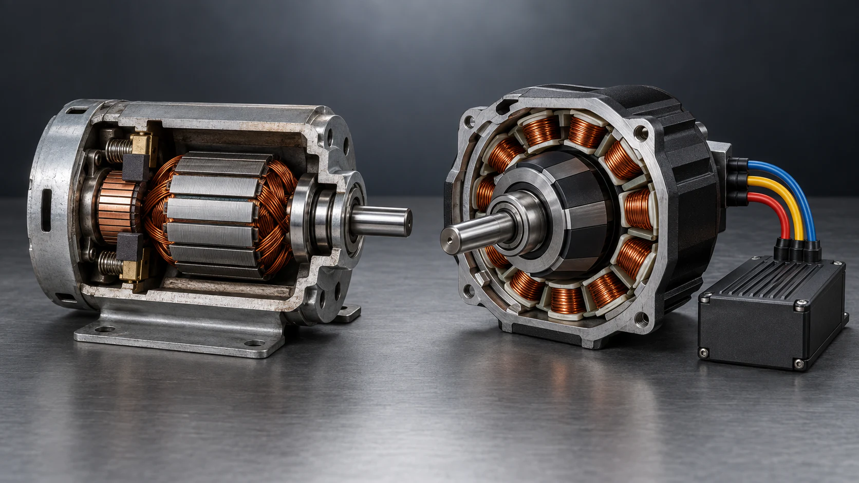
Figure 1. Illustrative cutaway, not to scale. A brushed motor switches armature current through brushes and a commutator. A BLDC system uses electronic commutation.
A brushed DC motor is usually the starting point for a cost-sensitive mechanism with intermittent duty, basic speed control, and acceptable brush service. A BLDC motor is usually the starting point for extended operation, limited maintenance access, compact packaging, or controlled low-speed and dynamic motion. Neither type can be approved without checking its actual operating point.
Choose a brushed DC motor when most of these conditions apply:
Choose a BLDC motor when most of these conditions apply:
The main difference is how current is switched to keep producing torque. That difference affects maintenance, control hardware, wiring, noise, and integration risk.
In a typical permanent-magnet brushed DC motor, stationary brushes contact a rotating commutator, which reverses current in the rotor windings as the shaft turns. The motor can run from a DC source; PWM regulates speed, and an H-bridge can add reversing and braking.
In a three-phase BLDC motor, permanent magnets rotate and the windings remain on the stator. A controller switches phase current according to rotor position, obtained from Hall sensors, an encoder, a resolver, or sensorless estimation. A plain DC connection is not a complete BLDC drive.
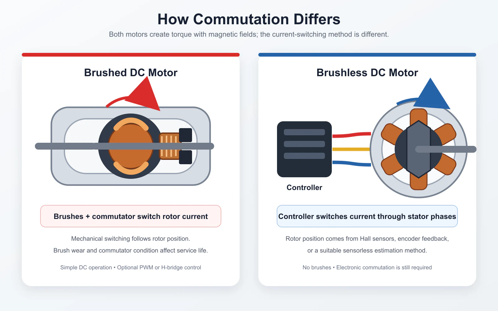
Figure 2. Mechanical commutation places the switching function inside a brushed motor. Electronic commutation moves that function into the BLDC controller and feedback system.
Use this table for screening; final approval requires candidate-specific data.
| Decision factor | Brushed DC motor | Brushless DC motor |
|---|---|---|
| Commutation | Mechanical brushes and commutator | Electronic controller or inverter |
| Basic drive | Can run from suitable DC; PWM or H-bridge adds control | Requires compatible electronic commutation |
| Routine wear | Brushes and commutator are wear items | No brushes; bearings and other system components still wear |
| Maintenance | Brush inspection or replacement may be required | Usually less routine motor maintenance, but not maintenance-free |
| Low-speed and start control | Direct torque response; controller and supply still limit current | Depends on controller, feedback method, tuning, and current capacity |
| Electrical and acoustic noise | Brush contact can cause arcing, EMI, and mechanical noise | Removes brush arcing, but PWM, commutation, bearings, and the load can still create noise |
| Efficiency | Must be checked at the operating point | Often favorable in comparable systems, but controller and gearbox losses must be included |
| Initial system cost | Often lower for a simple drive | Often higher because controller and integration are required |
| Service interval | Often constrained by brush and commutator condition | Often longer, subject to bearings, temperature, load, speed, and environment |
| Typical fit | Simple, intermittent, serviceable, cost-sensitive equipment | Extended-duty, low-maintenance, compact, or precisely controlled equipment |
Duty cycle changes the value of brushless operation. A brushed motor may suit an actuator that moves for a few seconds per cycle. The same brush service may be unacceptable in a two-shift conveyor or inaccessible equipment.
Record daily operating hours, starts per hour, direction changes, dwell time, peak-load duration, and available cooling. Do not describe an application only as “continuous” or “intermittent” when the real cycle can be measured.
Rated power alone is not enough. Specify continuous torque, starting or peak torque, permitted peak duration, minimum speed, normal speed, maximum speed, and acceleration time. Review the torque-speed curve and thermal limit at the intended supply voltage.
Mechanical output power can be estimated from torque and speed:
Power (W) = Torque (N·m) × Speed (rpm) ÷ 9.55
This calculation checks whether the stated torque and speed are consistent. It does not establish motor size by itself because winding temperature, controller current, cooling, and gearbox limits still apply.
Simple one-direction rotation may need only PWM speed adjustment. Reversing, active braking, stable low-speed operation, positioning, synchronization, and torque control may require additional controller functions or feedback.
Traditional sensorless back-EMF detection becomes difficult at standstill and very low speed because the measurable signal decreases with speed. When reliable starting under load or repeatable low-speed motion is required, evaluate Hall sensors or an encoder with the selected controller.
Compare the motor, controller, feedback, gearbox, integration, maintenance, downtime, and energy use at the real duty point. A lower purchase price may not reduce machine cost, while a lightly used device may not recover the added cost of a BLDC system.
Assume a machine needs 0.20 N·m at 1,800 rpm during normal operation. Its mechanical output requirement is:
0.20 N·m × 1,800 rpm ÷ 9.55 = 37.7 W
Now add the conditions that actually influence selection: the load requires 0.60 N·m for 1 second at startup, operates 16 hours per day, and sits behind a protective cover with limited airflow. The 37.7 W result is only the steady mechanical output. The selected system must also handle the startup current, stay within continuous winding and controller temperature limits, and repeat the cycle without exceeding the motor or gearbox ratings.
For this duty, a BLDC system is a reasonable starting point because long operating hours make service interval and thermal management important. It is not an automatic approval. A brushed candidate could still be valid if product-specific brush-life, temperature, torque-speed, and maintenance data meet the machine's requirements.
A BLDC selection is incomplete until the motor and controller are matched. Confirm voltage, continuous and peak phase current, Hall sequence, encoder supply and signal type, control inputs, braking, protection, and communication.
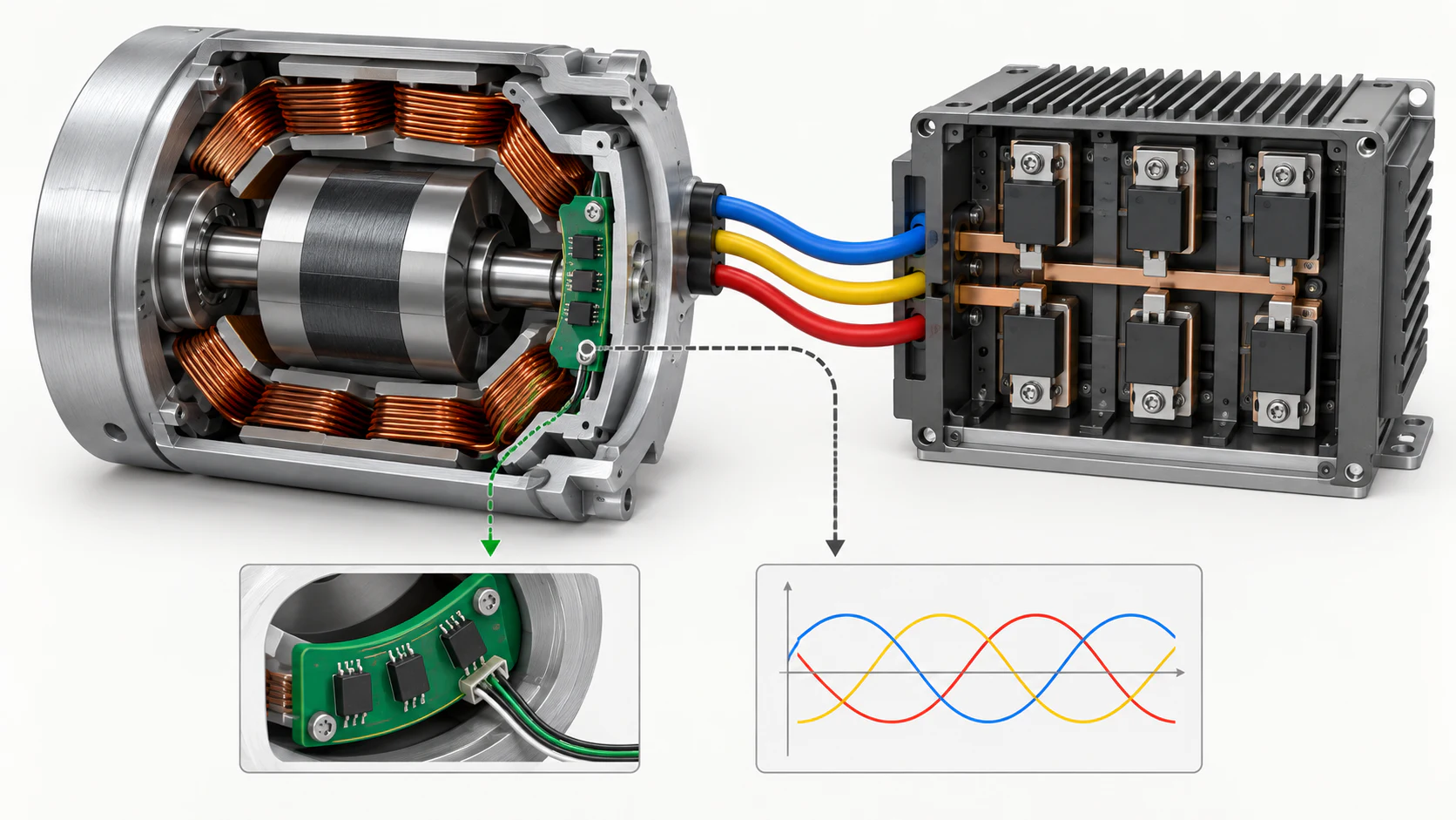
Figure 3. Simplified illustration, not to scale. Motor construction, power electronics, rotor-position feedback, current control, wiring, and software affect the final result.
Check regenerative energy during deceleration. A supply that delivers current may not absorb returned energy; the controller may need a braking resistor, bus-voltage protection, or a regenerative power source.
For a brushed motor, confirm continuous and peak current, PWM frequency, reversing, braking, and interference suppression. Simpler commutation does not remove controller and supply protection.
“Brushless” does not guarantee better efficiency, lower noise, longer life, or better low-speed motion in every comparison. Those results depend on the specific motor, controller, load, installation, and test point.
Peak torque is time-limited by current and temperature. If the load requires the peak value continuously, the motor is undersized even when it can start the machine once.
A gearbox changes speed and torque but adds loss, backlash, shaft-load limits, and its own thermal and service-life constraints. The calculated output torque must remain within the gearbox's continuous and peak ratings.
Brushed and brushless motors can both be designed for demanding environments, but the motor type alone does not establish IP protection, corrosion resistance, washdown suitability, or hazardous-location approval. Verify the complete assembly and its documented rating.
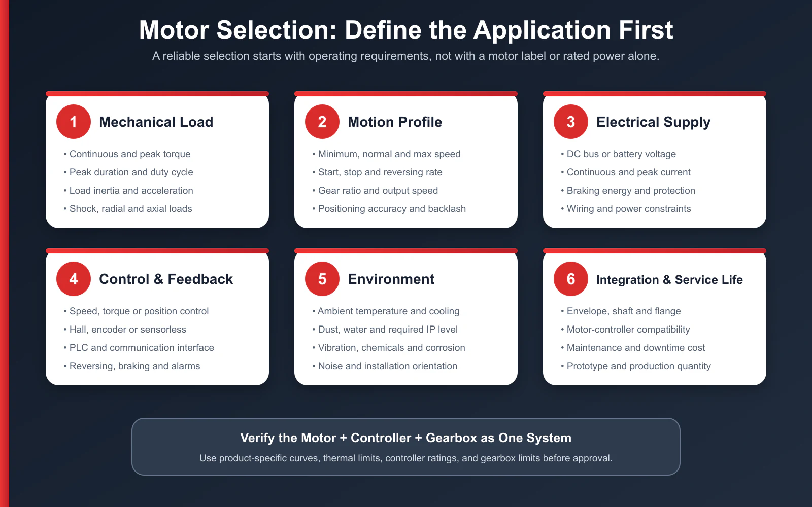
Figure 4. Use the same requirement set to compare brushed and BLDC candidates. Do not change assumptions between suppliers.
Send the same requirement set for every candidate so quotations are comparable:
TENCH can use this information to review a micro brushless DC motor or gearmotor or a high-power brushless DC motor with its controller and gearbox. See the Anjian medical equipment project for a documented brushless application and the TENCH motor selection FAQ for product-specific controller and duty-cycle questions.
No. A BLDC motor requires electronic commutation. The controller may be external or integrated into the motor assembly, but compatible drive electronics are still part of the system. Confirm voltage, current, feedback, phase sequence, control inputs, and protection before connecting the motor.
They do not require brush replacement, but they are not maintenance-free. Bearings, seals, cooling surfaces, cables, gearbox lubrication, and the controller may still require inspection. The interval depends on load, speed, temperature, vibration, contamination, and the product's instructions.
A BLDC motor often has a longer service interval because it has no brush-commutator wear. Actual life still depends on bearings, shaft load, speed, temperature, vibration, contamination, and controller setup. Compare product-specific data under relevant conditions.
It depends on the controller algorithm and the load. Conventional back-EMF methods have the least position information at standstill and very low speed. Hall sensors or an encoder are often the safer starting point when the machine must start under load or maintain repeatable low-speed motion.
Either type can be used when the complete system has suitable documented protection. Check IP rating, sealing, corrosion protection, insulation, drainage, condensation, temperature, and cable entry. Confirm any regulated or hazardous-location certification separately.
Send TENCH your voltage, continuous and peak torque, speed range, duty cycle, installation dimensions, control method, environment, and estimated quantity. We can compare the motor, controller, feedback, and gearbox requirements before recommending a configuration. Submit your application details to TENCH.


Leave a Reply