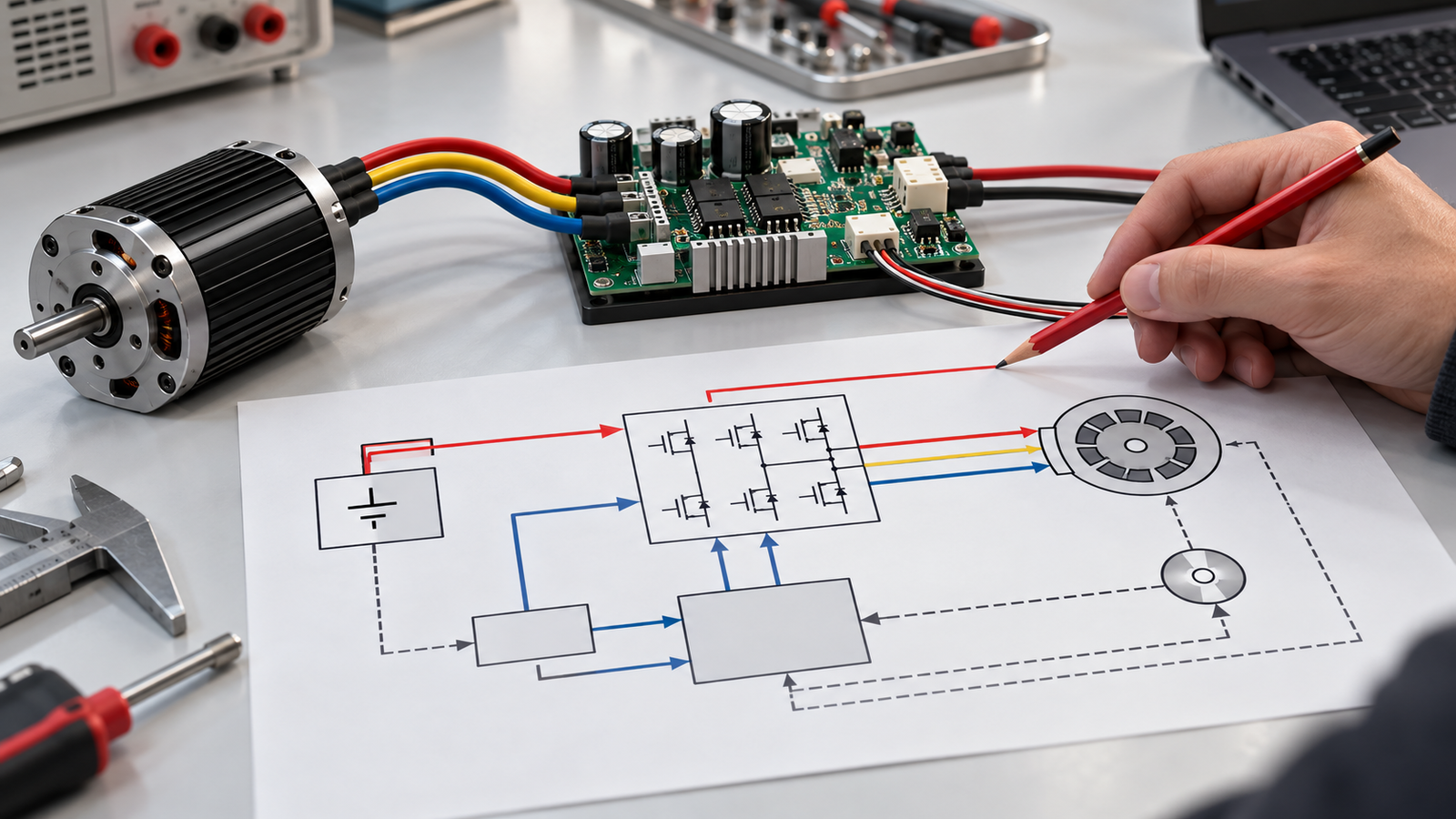
A BLDC motor control circuit diagram is a map of how electrical power, switching commands and rotor information meet. It is not automatically a build instruction. Some drawings show only functional blocks; others show a three-phase bridge, a controller's pins, or the cable connections for one particular motor. Before using any of them, identify what the drawing includes and which motor, driver and supply it was designed for.
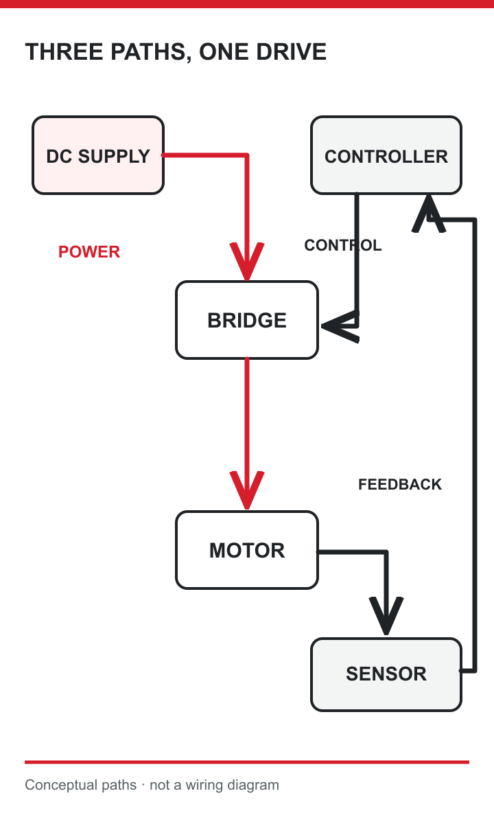
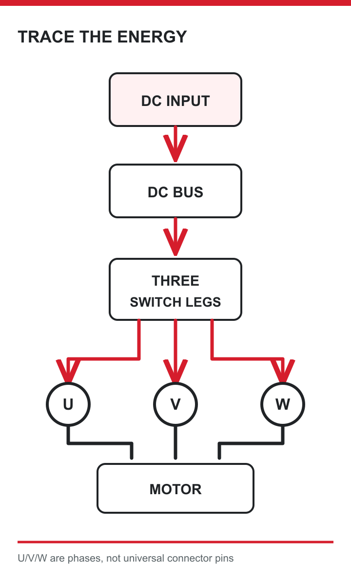
In a typical three-phase system, a DC supply feeds three switching legs. Their outputs energise motor phases U, V and W in a controlled sequence. A controller decides when to switch, gate drivers translate those commands for the power devices, and sensing or feedback tells the controller what the motor is doing. Current, voltage and temperature protection may interrupt that sequence when operation becomes unsafe.
This guide shows how to read those paths and where a diagram stops being enough. It does not provide a universal wiring schematic. The useful result is a set of questions you can take to the actual motor and controller data sheets: Are the ratings compatible? How is rotor position obtained? Which connections and protections are specified for this exact model?
Conceptual illustration; verify model-specific documentation.
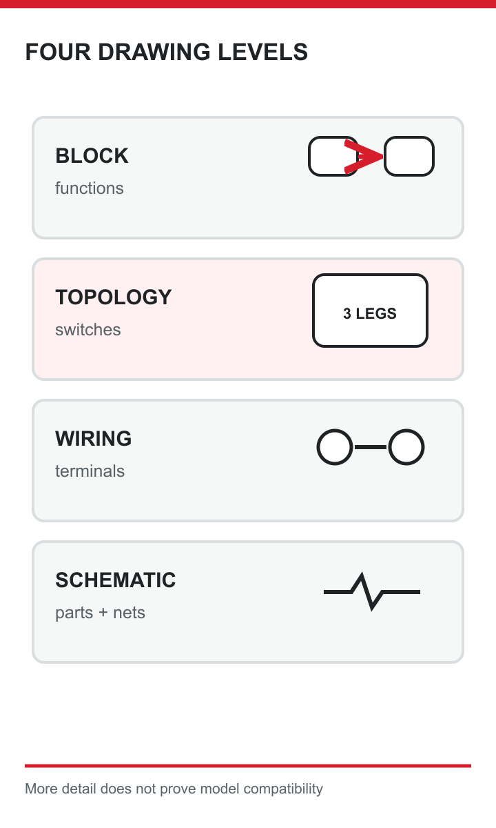
Start by reading the drawing's level of detail. A block diagram names functions such as controller, gate driver, inverter, sensors and motor. It helps you understand architecture but may omit every component value and pin number. A bridge-topology sketch shows three half-bridges and their phase outputs; it explains the switching path but may still omit the gate-drive supply, measurement circuits and fault handling. A wiring diagram connects named terminals between finished products. A schematic specifies components and nets for a particular design revision, but even that needs its accompanying bill of materials, data sheets and test conditions.
A simple test is to ask whether the drawing tells you exactly which part is connected to which verified terminal. If it says only 'Hall feedback' or 'current sensing', it is describing a function, not authorising a cable connection. Likewise, three lines labelled U, V and W are not evidence that two vendors use the same connector, phase order or colour convention.
Conceptual illustration; verify model-specific documentation.
Use the drawing to answer its intended question. For a purchasing comparison, a block diagram may be sufficient to identify whether the controller expects sensors. For installation, listed driver manuals and the model-specific connection and safety documents matter more. For circuit development, the complete schematic, device ratings, layout guidance and validation results are needed. Confusing these purposes is the first source of avoidable errors.
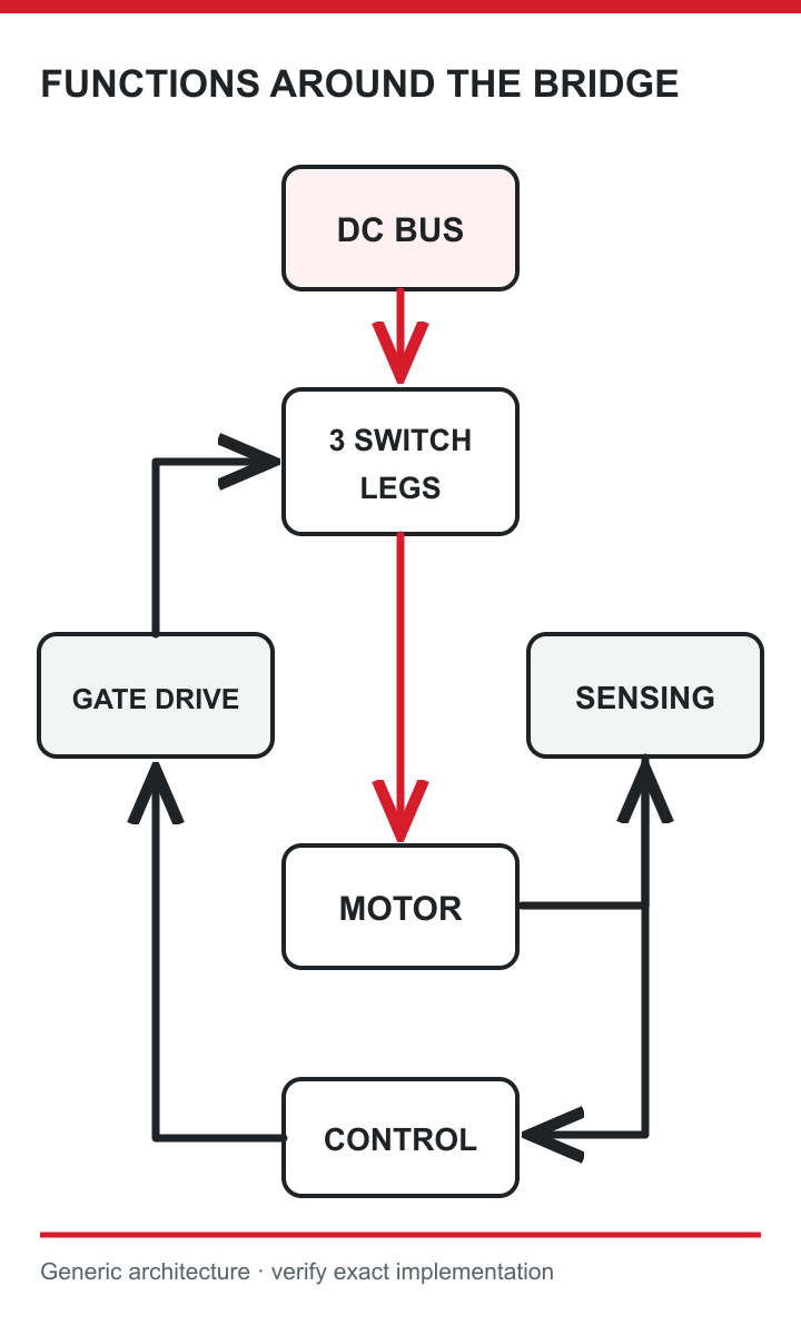
A BLDC motor control circuit diagram often centres on the power stage. In a conventional three-phase drive, the power stage is often drawn as three half-bridges: one for each motor phase. Each leg has a high-side and low-side switch, commonly a MOSFET in lower-voltage designs. The midpoint of each leg connects to U, V or W. This six-switch picture is the topology, not the whole controller. The gate-driver circuitry must move each switch cleanly between states, and the controller must coordinate the switches so that a leg does not short the DC bus through simultaneous conduction.
Look around the bridge for the supporting blocks. The DC input and bus capacitors supply pulsed current; current sensing gives the controller a way to limit or diagnose load; position information may come from Hall sensors or an estimated signal; voltage and temperature monitoring can contribute to fault decisions. A real design also needs appropriate isolation, grounding, thermal management and protection chosen for its operating environment. A diagram that omits these blocks may be simplified for teaching, not incomplete by accident.
Conceptual illustration; verify model-specific documentation.
Do not infer component ratings from the drawing alone. A symbol for a transistor says nothing about its voltage margin, current capability, switching losses or cooling. Nor does a '24 V' label by itself establish the permitted supply range or transient behaviour. Match each function to the manufacturer documentation for the selected controller and power devices before treating a topology sketch as an implementation.
A useful BLDC motor control circuit diagram can be read as a sequence of checks, not simply admired as a neat arrangement of symbols. Follow the power path first, then mark what the picture leaves unanswered.
A useful review question is where current enters, how it can flow during each switching state, and what stops it when a fault occurs. If an answer is absent, record it as an open verification point rather than borrowing it from a different controller. Bus capacitors and switches may store or deliver hazardous energy even when the nominal supply is called low voltage. This process makes a diagram a disciplined review aid without turning it into an unvalidated wiring instruction.
Conceptual illustration; verify model-specific documentation.
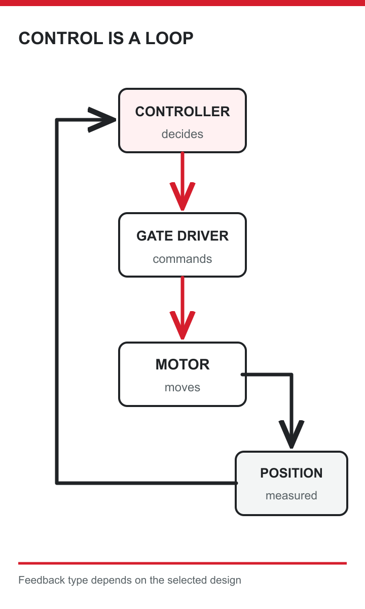
The control path starts with a command, such as a requested speed or torque, and ends with timed gate signals. Between those points the controller interprets feedback, chooses a commutation or control strategy, and applies safeguards. PWM modulates the switching; a gate driver provides the voltage and current needed at the power switches. The gate driver is not the same thing as the motor controller's decision logic, even when both functions live in one IC.
Feedback can be physical or estimated. Hall sensors provide discrete rotor-position information, while sensorless methods infer position from electrical signals. That difference matters at startup and very low speed, where back-EMF information may be weak. Current sensing supports torque control and overcurrent decisions, but a diagram's sensor symbol does not say whether the firmware uses it for regulation, protection or both. Follow each feedback arrow back to its source and forward to the decision it affects.
Conceptual illustration; verify model-specific documentation.
Finally trace what happens when the normal sequence fails. Look for fault pins, gate-disable paths, undervoltage lockout, overtemperature monitoring and documented restart behaviour. If the drawing omits these, the safe conclusion is 'not shown', not 'not required'. For a real motor/controller pair, confirm the signal type, connector mapping and fault response in the product manuals. A circuit can be electrically plausible yet unsuitable if its feedback and safety behaviour do not match the application.
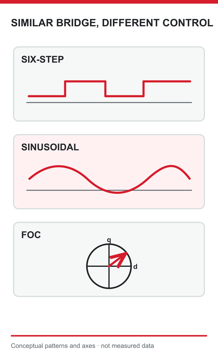
A six-step controller energises phase combinations in a sequence related to rotor position. Its educational diagrams often show commutation states and a comparatively simple logic flow. Sinusoidal control shapes phase currents more smoothly, while field-oriented control (FOC) calculates current components in a rotating reference frame. These are different control approaches, not three interchangeable labels for the same six-switch hardware.
The bridge topology may look similar across the approaches, which is why a single power-stage sketch can mislead. The differences lie in the sensing, processor capability, timing, firmware and tuning behind the switches. A diagram of FOC may show coordinate transforms and current loops that are absent from a six-step block drawing. Conversely, a six-step circuit illustration cannot establish that a controller supports precise torque regulation merely because it uses a three-phase bridge.
Conceptual illustration; verify model-specific documentation.
Choose by the operating requirement, then verify the actual product. Startup under load, low-speed smoothness, noise, dynamic response and efficiency can matter differently in a fan, pump or positioning axis. No diagram alone proves performance. Ask for documented control modes, feedback requirements, operating limits and test evidence for the exact motor and driver combination. That keeps a discussion of control theory connected to a practical purchase or engineering decision.
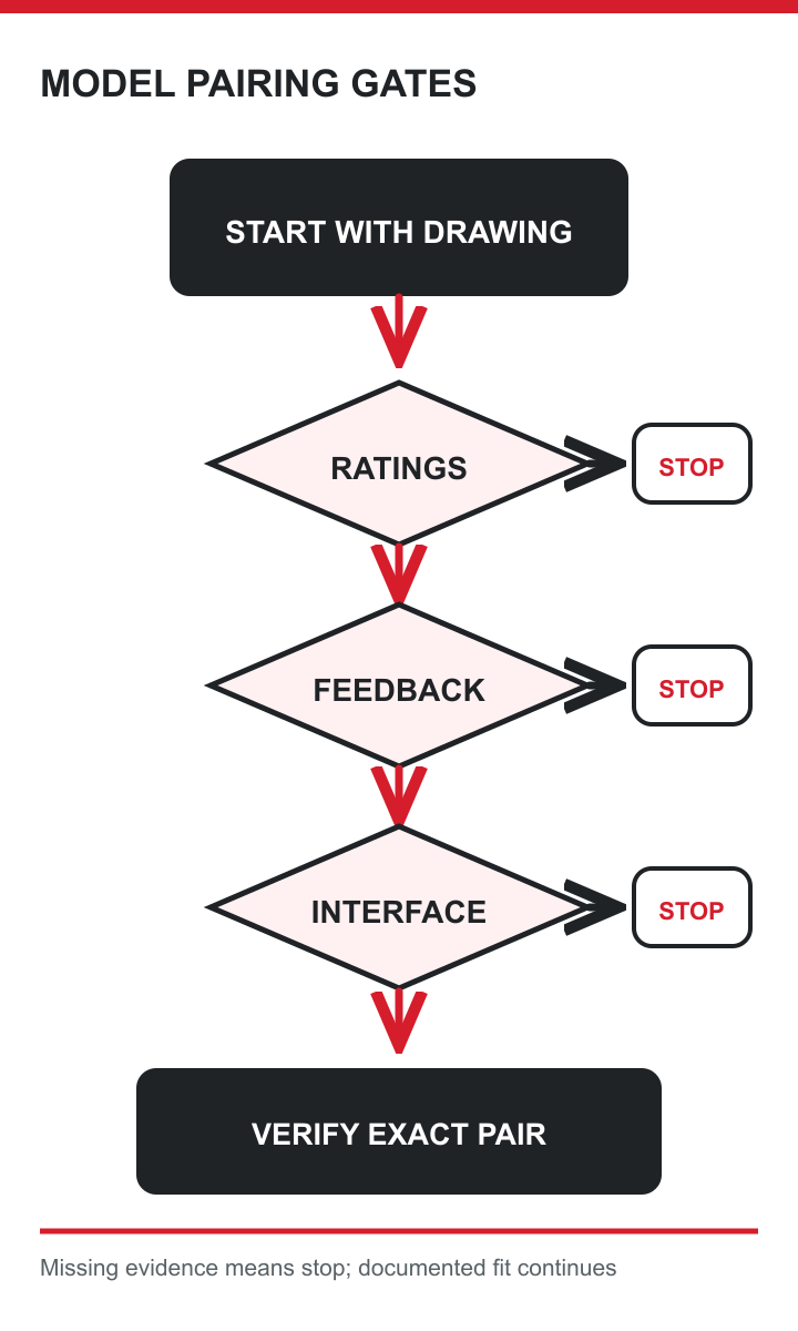
Use a compatibility sheet rather than selecting parts by matching the drawing's appearance. Record the motor's nominal and permitted voltage, continuous and peak current, speed range, winding and phase information, sensor type, connector and environmental limits. Record the controller's input range, continuous and peak output limits, feedback inputs, control interface, protection functions and thermal conditions. Compare the conditions attached to each rating; a peak figure for a short interval is not a continuous operating promise.
Then check the interfaces. Is the motor three-phase? Does it have Hall sensors, an encoder, or no physical position sensor? Does the controller support that feedback at startup and across the needed speed range? Are the control commands PWM, analogue, serial or another defined format? Are the connectors and phase labels actually documented for both products? A supplier drawing that omits these answers should trigger a request for model-specific documentation, not a guess.
Conceptual illustration; verify model-specific documentation.
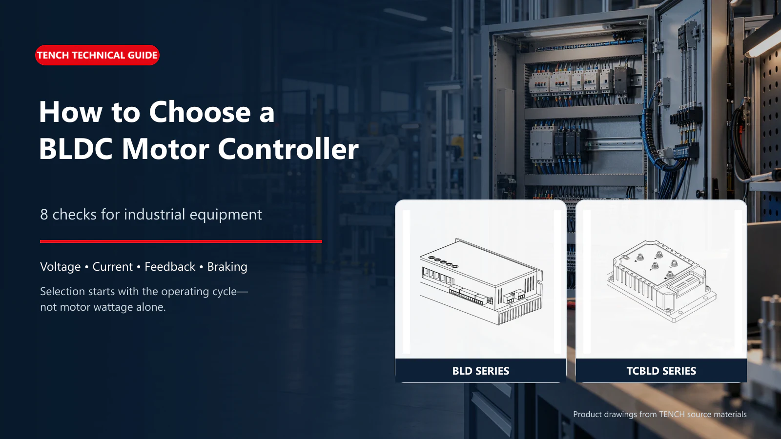
TENCH is a possible source for motors and controllers, but no product-family page should be read as proof that any two models form a compatible pair. A useful enquiry gives the required voltage, load, speed, duty cycle, feedback preference and operating environment, then asks for the exact paired motor/controller data sheets and connection instructions. That is a more reliable route than copying a pinout from a search result.
A compact single-chip fan-driver circuit can be useful evidence of one design approach: it may integrate commutation logic and power switching for a defined motor class and supply range. It is a poor universal template. The supported current, number of phases, startup method, sensor assumptions, thermal path and protection details may all be specific to that IC and the example circuit around it.
For example, suppose a reader finds an attractive diagram with only a few external components. It may be tempting to scale it to a larger industrial motor by changing a transistor or supply. That misses the interactions among switch stress, gate drive, bus energy, current measurement, heat dissipation and firmware timing. Even a schematic from a respected source is usually an example for its named part under stated conditions, not a blanket endorsement of modifications.
Before transferring any example, identify its part number and the application conditions printed beside it. Compare them with the proposed motor and duty cycle. Where the example omits a protection block, check whether the function is integrated into the IC, delegated to another component or simply outside the drawing's scope. If those answers are unavailable, use the example for concept learning only. A model-specific manufacturer reference design and qualified review are the right starting points for engineering a new power stage.
Before energising any motor drive, separate educational understanding from implementation approval. Confirm the exact part numbers, supply range, current limits, phase and sensor connections, required protective components and permitted operating conditions in the manufacturers' data sheets. Check the controller's published wiring guide and firmware configuration for the intended motor. If documents disagree, stop and resolve the conflict with the supplier or qualified engineer.
A design review should also ask how faults are detected and made safe. Consider current limiting, loss of rotor information, stall, reverse energy, bus transients, temperature and unintended simultaneous switching. Record the expected response to each condition and how it was validated. For installed products, follow their safety and commissioning instructions; for a new circuit, include electrical, thermal and layout verification rather than relying on a neat diagram.
The central lesson for any BLDC motor control circuit diagram is to read it as evidence of architecture, then prove the exact implementation separately. Use the drawing to trace power, control and feedback, and use model-specific documentation to establish ratings, connections and protections. Where those details are missing, the next step is to obtain them, not to invent a wiring decision.



Leave a Reply