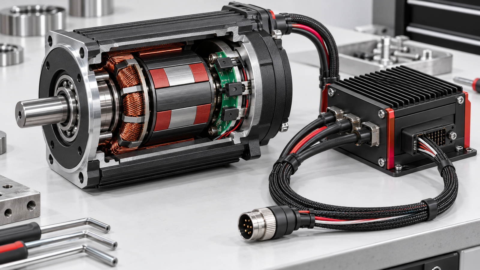
A Hall sensor in BLDC motor systems gives the controller a position clue, not a device that drives the windings. As the rotor magnets pass the sensor, its output changes state. A controller can combine those changes with its commutation logic to energise the appropriate motor phases. In a common three-sensor, three-phase arrangement, the combined outputs identify six broad electrical sectors. That is enough information for many block-commutated motors to start and run, but it is not automatically a precise measurement of shaft angle.
The practical decision is therefore about the complete motor–sensor–drive system. Does the motor have Hall sensors? Which supply and signal levels do they require? Can the chosen controller decode their actual transition order, and does the application need speed regulation or precise positioning? Those questions cannot be answered from a generic six-step picture or a connector that happens to fit. This guide separates the jobs Hall feedback can do from the ones it cannot, then gives a model-specific verification sequence for an OEM or maintenance engineer.
A Hall-effect device responds to magnetic field. The search phrase “hall sensor in bldc motor” asks how this magnetic change becomes a signal the controller can use. In a BLDC motor, sensors placed near the rotor produce digital transitions as the rotor magnets move past them. The drive reads the resulting pattern as an indication of the rotor's electrical sector. The sensors are not measuring phase current and do not supply motor power; the inverter in the controller switches current through the stator windings. Texas Instruments' motor-control guidance uses the sensor states to determine when electrical commutation should change.

Original conceptual visual; explanatory details remain in adjacent article copy.
An individual output has little meaning without its companions and the motor's design. Three outputs can form a code that changes as the rotor turns, but the order of those codes depends on sensor placement, winding phase order and direction. The logic supply and output type also matter: a controller input expecting one voltage or pull-up arrangement may not read another sensor reliably. A valid test is not simply seeing a voltage change. It is checking the documented sequence under a controlled rotation and confirming the drive interprets it for the named motor.
This distinction matters during troubleshooting. A stationary motor with a fault message may have an open sensor wire, an incorrect supply, wrong phase pairing or a controller configuration issue. It does not follow that the Hall device itself has failed.
In a common three-phase motor with three Hall channels, the controller observes a sequence of six usable combinations during one electrical revolution. Each transition tells it the rotor has entered another sector. Under block or six-step commutation, the inverter changes which phases are driven as the state changes. That is the central job of Hall feedback: timing electrical switching to the rotor rather than energising windings blindly at standstill.
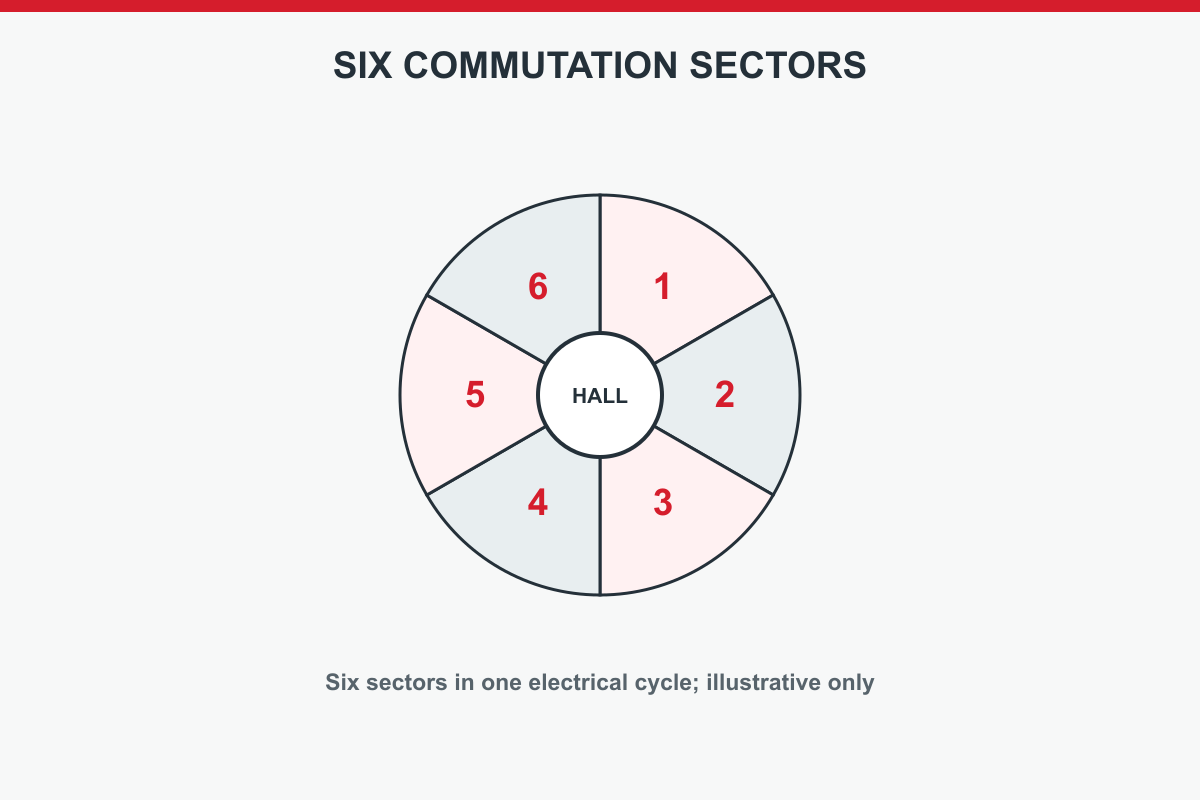
Original conceptual visual; explanatory details remain in adjacent article copy.
Do not turn a generic state table into a wiring instruction. Manufacturers may use different sensor order, phase labels, connector numbering or direction conventions. A sequence that is valid for one motor can be shifted or reversed for another. An invalid combination such as all inputs low or all high may indicate a fault in a particular design, but the drive manual—not an internet diagram—must define how that model handles it. The Texas Instruments note and Oriental Motor's control explanation describe the method; neither supplies the manufacturer's model-specific pinout.
For a commissioning check, record the three states while the motor is rotated by a safe, documented method, compare their order with the motor and controller documents, then check that forward and reverse commands follow the intended mechanical direction. Do this before interpreting speed or torque performance.
Hall feedback is often described as “position feedback,” but that phrase hides three different jobs. First, commutation uses the sector code to decide when to switch winding current. Second, speed regulation can estimate speed from the time between successive transitions. Third, positioning asks where the shaft or load is, often within a far narrower tolerance than a Hall sector. A system can accomplish the first two while failing the third.

Original conceptual visual; explanatory details remain in adjacent article copy.
At low speed, transitions become sparse. Speed estimates may need filtering and the response depends on controller design. During a stop, Hall signals tell the drive only which sector the rotor occupies; they do not by themselves prove that a shaft reached a specified angular point, nor that a load held there under disturbance. Oriental Motor's stopping-accuracy discussion makes clear that stopping behaviour belongs to the whole motor and control arrangement. The requirement might instead call for an encoder, homing procedure, brake or closed-loop servo controller.
Write the machine requirement in operational terms before choosing a sensor: “start against this load,” “hold this speed within this tolerance,” or “return to this position after power loss.” The same Hall-equipped motor may be suitable for one statement and inadequate for another.
Electrical angle is not necessarily the same as the shaft's mechanical angle. A motor with multiple pole pairs repeats its electrical pattern several times during one mechanical revolution. If there are p pole pairs, one shaft turn spans p electrical turns. A controller can use the Hall pattern for commutation because it follows the magnetic field it must energise, but a six-state pattern alone does not identify a unique absolute shaft position across all pole pairs.

Original conceptual visual; explanatory details remain in adjacent article copy.
That relationship also affects calculations from Hall transitions. A speed calculation must use the actual number of transitions per mechanical revolution for the named motor and sensor arrangement. Assuming the pattern repeats only once per shaft turn can produce a wrong speed estimate. Likewise, a drawing showing six sectors is not evidence of a fixed number of degrees at the output shaft. Gearing adds another conversion between motor shaft and load.
Before configuring a controller, obtain the pole-pair count and the manufacturer's Hall sequence or equivalent commutation data. If the documentation is unclear, record the uncertainty and ask the supplier. Do not infer a universal Hall truth table from another product family. The distinction is particularly important when a system also claims position or stopping accuracy.
Hall-sensored and sensorless drives solve the same commutation timing problem with different evidence. A Hall-sensored controller reads magnetic rotor-state transitions. A sensorless controller commonly estimates rotor position from electrical measurements such as back electromotive force. Back-EMF information becomes easier to use once the rotor is moving; starting under load and very low-speed operation may therefore require a specific startup strategy. The actual performance is controller- and application-dependent, not a universal ranking.
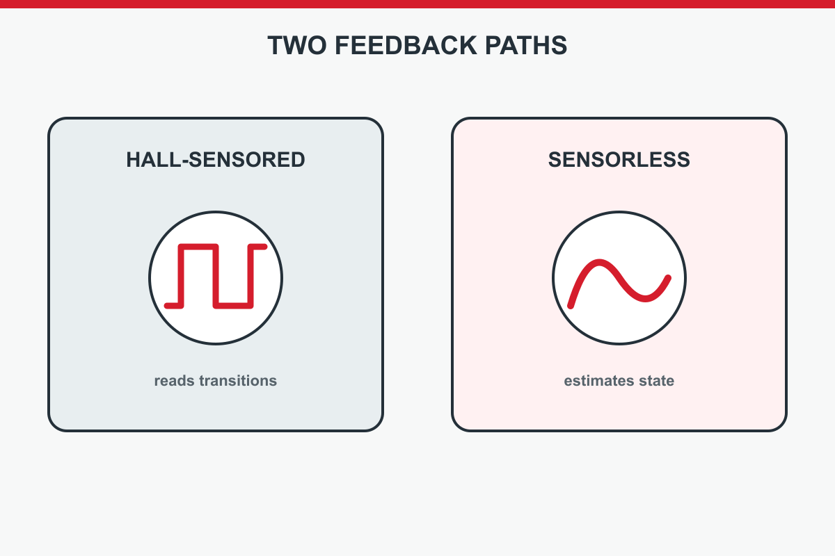
Original conceptual visual; explanatory details remain in adjacent article copy.
| Decision point | Hall-sensored approach | Sensorless approach |
|---|---|---|
| Rotor state at rest | Sensor pattern can indicate an electrical sector | Electrical estimation may require an alignment or startup sequence |
| Hardware | Adds sensors, wiring and connector checks | Avoids those components but depends on estimation and drive design |
| Low-speed or variable load | May offer more direct commutation feedback | Must be validated against the drive's low-speed limits |
| Failure modes | Sensor supply, wiring or state-order faults | Estimation, startup or signal-quality faults |
The table is a selection aid, not a promise of torque, efficiency or reliability for every product. Compare actual startup load, speed range, cable environment and service requirements. Anaheim Automation's BLDC system-selection guidance supports evaluating motor and controller together. A sensorless fan running steadily is not the same case as an axis that repeatedly starts, reverses and holds.
An encoder can report many more positions per revolution than the broad sectors produced by a typical Hall commutation arrangement. That extra information may be necessary when a machine must regulate position tightly, detect small following errors, or coordinate motion with another axis. It is not automatically required for a pump or conveyor whose main outcome is running at an acceptable speed. Decide from the tolerance and behaviour, not from a belief that more feedback is always better.
The encoder type matters as well. An incremental encoder measures changes in position and may need a reference or homing step after power loss. An absolute encoder can report position according to its own interface and resolution, but only if the drive supports that exact protocol. Some systems use Hall signals for commutation and an encoder for the position loop; others use different methods. ElectroCraft's drive guidance illustrates that feedback choices must fit the controller. Never assume that adding an encoder connector to a Hall motor automatically upgrades a speed controller into a positioning servo.
For a hall sensor in bldc motor pairing, the phrase “compatible” means a set of documented checks, not a yes/no inferred from the words “Hall sensor.” Start with the exact motor and driver part numbers, including winding, sensor and firmware options. Match the sensor supply voltage and current requirement to the controller output; then match the Hall output type and high/low levels to its inputs. Verify connector pin numbering, common ground, shielding and cable length against both manuals. Next compare the expected state sequence and phase order in each direction.
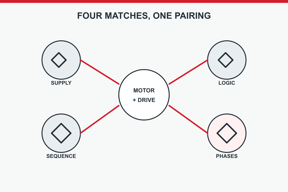
Original conceptual visual; explanatory details remain in adjacent article copy.
The electrical and mechanical application still has to fit: DC bus range, continuous and peak phase current, speed range, startup load, thermal duty and protective behaviour. A motor can generate valid Hall transitions yet be unsuitable for a controller's current capability. Conversely, correct power ratings cannot rescue a mismatched feedback interface. Request a model-specific pairing statement or commissioning instructions from the supplier when the documents do not answer these questions.
Use a written matrix with columns for “motor document,” “driver document,” “measured on assembly,” and “open question.” That prevents a plausible generic wiring diagram from being treated as certified compatibility. Anaheim Automation's system-design approach is useful here, while exact values must come from the selected models.
Start with the least invasive evidence. Read the controller's fault code and the exact motor and drive manuals. Confirm the correct motor variant and sensor option are installed. With power isolated and the stored-energy procedure followed, inspect the connector, pins, cable strain relief and obvious damage. Verify the stated sensor supply and return at the correct points using the manufacturer's safe test method. Do not probe a running high-energy drive or move machinery merely to satisfy a generic checklist.
If the manuals allow a signal check, observe the three Hall outputs while the rotor is moved by an approved procedure. Record whether each channel changes and whether the combined states follow the expected order. For example, one channel stuck high may suggest wiring, supply, sensor or input trouble; it is not a conclusive diagnosis of the sensor alone. A complete but reversed order may point to direction or phase association. Compare the observations with the exact controller configuration before changing wires.
Finally, test the commanded direction, startup and fault recovery on the assembled axis under a controlled load. Stop if the behaviour is unexpected. Preserve the measured sequence, settings and fault log so a supplier can distinguish a failed component from an interface mismatch.
A Hall transition marks a sector boundary, not the instant a mechanical load stops. The motor and driven mechanism keep moving while torque changes, current decays and inertia is dissipated. The amount of overrun depends on speed, inertia, friction, deceleration command, controller mode, braking arrangement and load direction. Oriental Motor's stopping-accuracy material compares stopping methods, rather than claiming that a Hall-equipped motor has a universal stop tolerance.
If the application is an indexer or lift, define the allowable stopping error at the load, not just at the motor shaft. Account for gear ratio, backlash, flexible couplings and any power-loss condition. Ask whether the drive actually closes a position loop, whether homing is needed, and what happens when the sensor signal is lost. A brake may be required to hold a vertical load; Hall feedback itself does not provide holding force.
Validate stopping accuracy empirically across the real speed, load and temperature range. One successful empty-axis stop does not cover the worst case. If the tolerance cannot be demonstrated from documented control capability and a repeatable machine test, specify a more suitable feedback and control arrangement.
TENCH publishes brushless motor, driver and motion-control product families, but the right question is about a named combination. Send the precise motor and driver model identifiers, the Hall-sensor or encoder option, supply voltage, load and duty cycle, commanded speed range, required startup behaviour and any positioning tolerance. If the drive will sit in a cabinet or use a long sensor cable, include those conditions. Ask for the applicable wiring diagram, sensor supply and logic specification, Hall transition order and controller parameter guidance for those exact parts.
The useful outcome is a scoped technical response: a documented pairing, a set of conditions to verify, or a clear statement that a requirement needs a different product. It is not a blanket guarantee based on a motor family name. Where the task is precise positioning, say so at the start; a speed-control solution may be inappropriate even if it spins the motor. Where a load must hold after power loss, raise the holding and safety requirement separately.
Use TENCH's published product information as a starting point and require model-specific documentation before procurement or installation. This keeps the supplier conversation focused on the interface that matters rather than a generic Hall-sensor explanation.
A search for “hall sensor in bldc motor” leads to a short selection path when the questions are kept distinct. First, define whether the machine needs commutation, speed regulation, positioning or some combination. Second, identify the exact motor winding, pole count and installed sensor option. Third, compare the Hall supply, outputs, sequence and pinout with the named drive. Fourth, check bus voltage, phase current, startup load and duty cycle. Fifth, test direction, low-speed operation, stopping and faults on the assembled machine using safe manufacturer procedures.
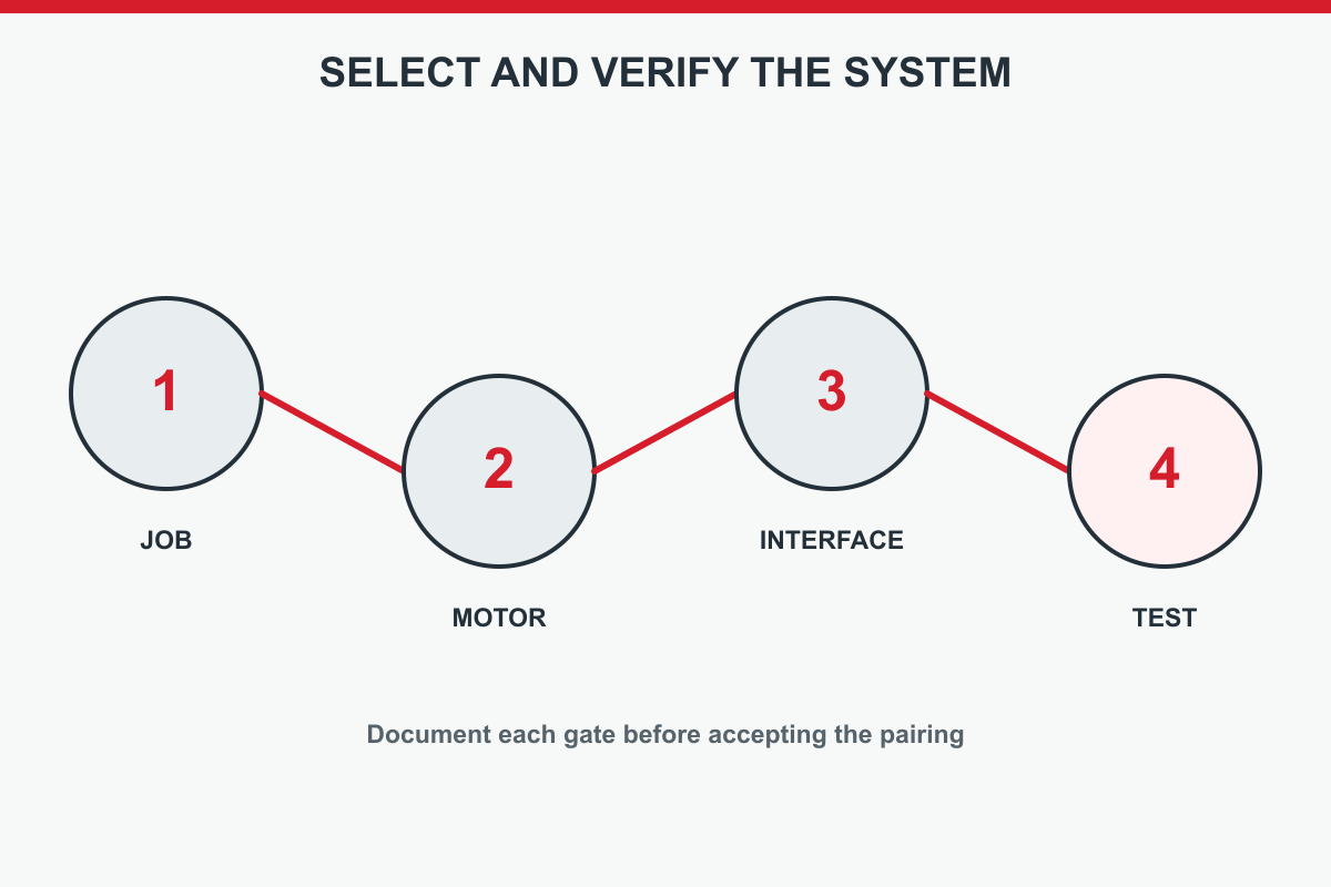
Original conceptual visual; explanatory details remain in adjacent article copy.
Record every unknown rather than filling it with a generic six-step chart. Hall sensors can make BLDC commutation practical at startup and provide useful speed feedback, but they do not alone certify precise shaft position, stopping accuracy or compatibility with any controller. A documented motor–driver pairing and controlled acceptance test are the reliable final decision. If exact model information is missing, request it before connecting or purchasing the parts.



Leave a Reply