Are brushless DC motors more efficient? Often they are when compared with a similarly sized brushed DC motor doing the same job, but the answer is not a property of the nameplate alone. Removing a physical brush and commutator can eliminate contact losses; an electronic drive, winding resistance, magnetic losses and mechanical friction still consume power. At one speed and torque the advantage may be meaningful, while at another it may narrow or disappear. A comparison with an AC motor is even less useful until the designs and operating points are specified.
If you are choosing a drive for a machine, the useful question is not “which technology has the highest advertised percentage?” It is “how much electrical power does each complete drive need to deliver my required shaft torque and speed for my actual duty cycle?” This guide explains the measurement boundary, the losses behind the answer, and a practical way to request comparable data. It deliberately does not assume that any particular TENCH motor is more efficient than an untested alternative.
The comparison most readers mean is brushless DC versus brushed DC. In the brushed design, current changes direction through a mechanical commutator and brushes. A brushless design uses electronic switching instead. That can reduce brush contact friction, wear and associated electrical losses, especially when the rest of the design is well matched to its controller. It does not mean every brushless model beats every brushed model. Differences in motor size, winding, magnet design, gearing and drive electronics can outweigh the absence of brushes.
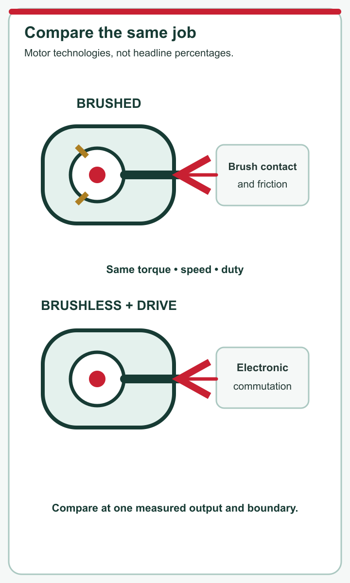
Brush contact and electronic commutation are different mechanisms.
“More efficient than AC” is a different claim. AC is a broad supply and motor category, not a single reference machine. A modern AC motor and variable-speed drive may perform very well at one duty point; a small BLDC system may perform well at another. Comparing a bare BLDC motor with an AC motor-plus-inverter, or comparing peak ratings at different loads, answers no fair engineering question.
For a first pass, hold the useful output constant: same torque at the same speed, sustained for the same duration. Then compare electrical input at the same boundary. Ask whether the quoted figure includes the controller and any gearbox. If those details are missing, treat the percentage as a clue for further testing, not a purchasing decision.
Efficiency is a ratio, not a fixed label. Mechanical power at a rotating shaft is torque multiplied by angular speed. Electrical input is the power entering the equipment at a specified point. Efficiency is shaft power divided by that input, multiplied by 100 for a percentage. Both measurements need to represent the same steady operating condition. A no-load speed figure and a rated current figure, taken separately, cannot be combined into a trustworthy result.

Measure input and output at the same defined boundary.
The boundary changes what the number means:
| Comparison boundary | Input to measure | Output to measure | What the result tells you |
|---|---|---|---|
| Motor only | Power at the motor terminals | Motor shaft power | Performance of the motor, excluding drive losses |
| Motor and controller | DC supply or drive input power | Motor shaft power | Performance of the controlled drive at that point |
| Geared assembly | Input to the complete drive | Output after the gearbox | Power delivered where the machine uses it |
These are different, valid metrics. The problem arises when two figures from different rows are compared as though they were identical. A gearbox may lower output speed and increase available torque while introducing its own losses; it does not create energy. A controller adds switching and conduction losses, yet may also permit operation at a more appropriate speed. Specify whether auxiliary loads such as cooling are included, particularly for a complete installation. For most selection decisions, the input boundary should reflect the equipment you will actually buy and operate.
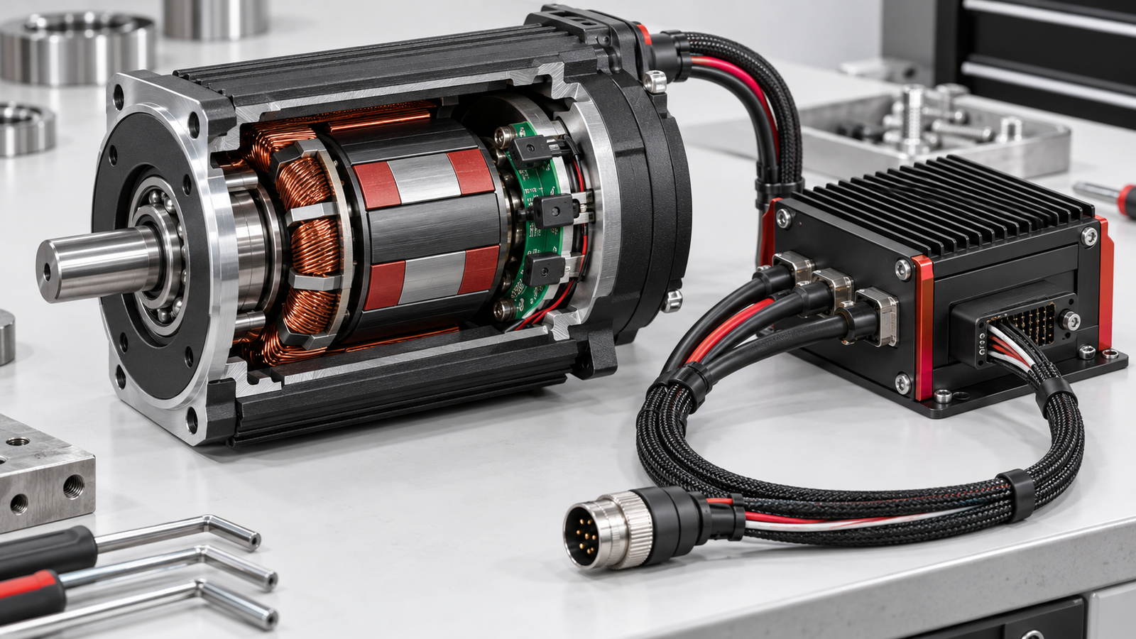
Brushless commutation removes the sliding contact between brushes and commutator. Less contact friction and no arcing at that interface can help convert more input power into useful output. Electronic commutation can also support precise speed and torque control when the controller, sensors or estimation method are suited to the application. These are mechanisms for a possible advantage, not a promise of a particular percentage.
Several losses remain. Current through the windings creates heat; higher current at a demanding torque point may increase that loss. Magnetic material has losses as its field changes. Bearings, seals and air movement consume mechanical power. The inverter or controller uses power to switch current and has its own conduction losses. A gear train, if present, introduces another boundary and another loss source. Thermal behaviour matters because resistance and operating conditions can change as the system warms.

Removing brushes does not eliminate every motor loss.
This explains why a simplistic “brushless equals efficient” statement can mislead. A poorly matched controller may waste energy even when the motor itself is capable. A drive operated far from its useful range may have a disappointing system figure. Conversely, a brushed solution operating briefly at a well-chosen point may be adequate despite lower theoretical potential. Compare real options on the same basis and examine which losses dominate at the required load rather than attributing the entire difference to brushes.
A motor does not spend a normal working day at a single catalogue point. It may start under load, accelerate, hold a steady speed, reverse, pause and idle. Each part of that cycle demands a different torque and speed. The energy bill and heat load depend on the time the drive spends at each point, not only on the best efficiency it reaches in a test. Light-load behaviour can be especially important for machines that spend many hours waiting or running below rated output.
Plot or obtain efficiency over the expected torque-speed range. Mark the continuous operating point, the peak-load events and any low-speed holding or frequent starts. Check continuous torque and thermal limits separately from short-duration peaks. If the application requires a gearbox, use the output curve for the chosen ratio and measure at the machine side where possible. A motor selected by maximum rated power alone may be oversized for the daily duty and inefficient for much of its use.
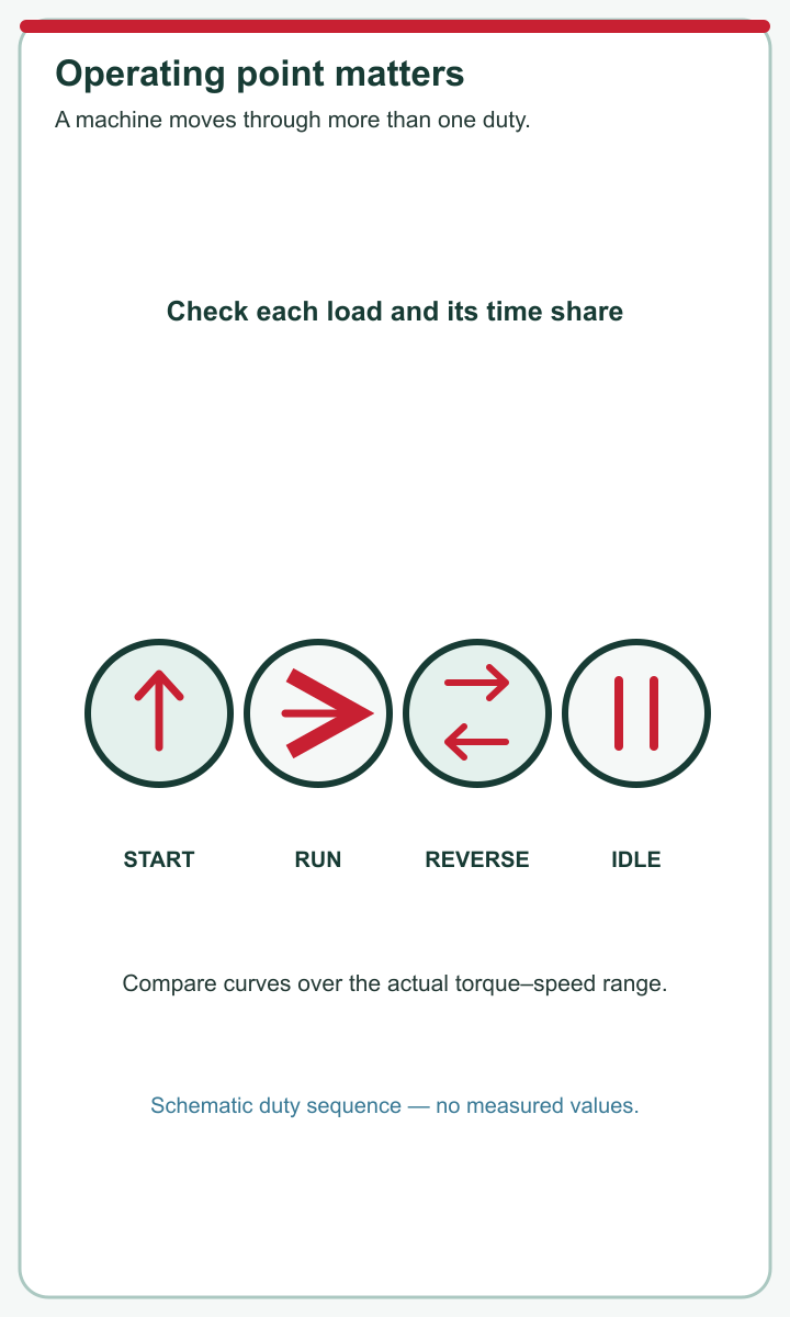
Operating conditions vary across a machine duty cycle.
A useful comparison can weight input power by time at each duty point. For example, a machine that spends most of its shift at a modest load should not be judged mainly by a brief peak-speed test. You do not need to invent a universal duty-cycle formula: record the real sequence, choose representative points, and ask suppliers for measured values or curves at those points. State ambient and cooling assumptions so that a warm, continuous test is not silently compared with a cold, short one.
Use a matched-output test, not two unrelated brochure percentages. A competent engineer or test laboratory can follow these steps with calibrated equipment and the manufacturer's electrical-safety procedures:

Compare candidates at matched useful output and equivalent input boundaries.
If you cannot run a bench test, contact TENCH to request a manufacturer's efficiency curve, drive losses, test method and controller model. Ask whether the figure is motor-only or for a complete assembly. Missing data is itself a decision risk. A supplier that can document the matched operating points gives you a firmer basis for selection than one that offers only an unsupported “high efficiency” claim.
Even a verified efficiency advantage is only one part of a drive decision. Heat affects enclosure design and continuous duty. Brush wear and replacement may matter in a hard-to-access machine, while an electronic drive brings its own cost, integration and failure considerations. Required speed control, torque response, acoustic behaviour, electromagnetic compatibility and available supply must be checked against the application. A geared drive may simplify torque delivery yet change the overall efficiency and maintenance picture.

Efficiency is one factor in selecting a complete motor system.
The sensible trade-off depends on run hours. An improvement during a continuously operating shift may justify a higher initial price; for a low-duty mechanism, the energy difference may be smaller than the cost of redesigning its controller or wiring. That is a calculation using measured input power, annual operating time and purchase and maintenance costs—not a reason to assume brushless always wins. Safety or precision requirements may also outweigh a small energy difference.
Keep adjacent decisions separate. A brushless motor is not automatically the right size, and a more efficient bare motor does not guarantee a more efficient geared assembly. Nor does a lower electrical input at one point prove superior lifetime. Ask for the operating curves and specifications that correspond to the actual machine, then rank efficiency alongside controllability, thermal margin, service needs and total cost.
If you are considering a TENCH motor, take the duty profile to the selection conversation. State the required output torque and speed, continuous and peak periods, supply voltage, available controller, gearbox ratio if any, and environmental and cooling constraints. Ask for the exact motor and drive model, the measurement boundary behind any efficiency curve, and data at your working points. If the answer is a single percentage, ask what load, speed, temperature and drive configuration produced it.
This is also where to confirm compatibility: controller or driver type, feedback arrangement, connectors, gearing and continuous thermal limits should come from documentation for the specific assembly. TENCH's customer profile provides relevant product-selection context, but it is not an efficiency test for a named motor. No unsupported TENCH performance claim should replace a model-specific datasheet or measured comparison.
So, are brushless DC motors more efficient? They often can be than comparable brushed DC motors, because they avoid brush-contact losses. The practical answer for your machine comes from a matched-output, motor-and-drive comparison across its duty cycle. Define the boundary, obtain data at the real operating points, check heat and integration, and only then decide whether the likely energy benefit is worth the complete system choice.



Leave a Reply