You have a motor marked “brushless” and need to know which supply and controller it requires. Are brushless motors AC or DC? If the unit is a brushless DC (BLDC) motor, the usual answer is DC at the drive system’s input, with an electronic controller switching current through the motor windings. The changing current inside the motor is the source of the confusion: it does not mean you can connect the motor directly to an AC wall outlet. Nor does “DC” mean a bare BLDC motor can be run like a two-terminal brushed motor.
The useful question is not just which label appears on the motor. It is where power enters the complete motor-and-drive assembly, what the controller does with it, and what the exact product documentation permits. A drive can have one kind of supply connection and a different-looking electrical output to its windings. Keep those points separate and the terminology becomes much less mysterious. The practical result is a safer specification conversation: identify the motor and controller together before deciding how to power either one.
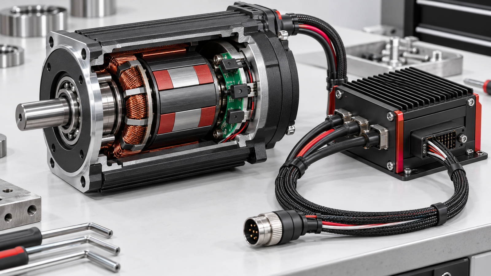
A BLDC motor is normally described as a DC motor because its drive operates from a DC link and electronic commutation replaces the brush-and-commutator arrangement of a conventional DC motor. Nidec describes a permanent-magnet rotor, stationary coils and a semiconductor drive circuit that switches current to those coils. Renesas likewise describes the fixed stator windings and externally controlled current that make the rotor turn. That is the engineering basis of the name, not a promise that every terminal on a complete product always carries steady DC.
Think of three layers. First is the available electrical supply. Second is the drive or controller, which interprets commands and switches power. Third is the motor’s individual phase windings, whose current changes in a timed sequence. Asking whether the motor system is AC or DC without saying which layer you mean invites two apparently contradictory answers. The drive may be powered from a DC source, yet its phase outputs alternate as it commutates. An integrated product may contain additional conversion electronics, so its permitted input must be checked on its own label and documentation.

DC supply, drive and motor phases are distinct electrical boundaries.
The word “brushless” alone identifies the absence of mechanical brushes; it does not give you a safe input-voltage or wiring specification. If the model number or controller is unknown, stop at the general explanation and obtain the exact documentation before connecting power.
In a brushed DC motor, brushes and a rotating commutator mechanically transfer and reverse current in the rotating winding. A BLDC motor moves the electrical switching into a controller. The permanent-magnet rotor turns while coils fixed on the stator are energised in sequence. Nidec notes that the dedicated drive circuit is essential; Renesas explains that control of the stationary coils changes the magnetic field that pulls the rotor around.
A simple way to keep the layers straight is this:
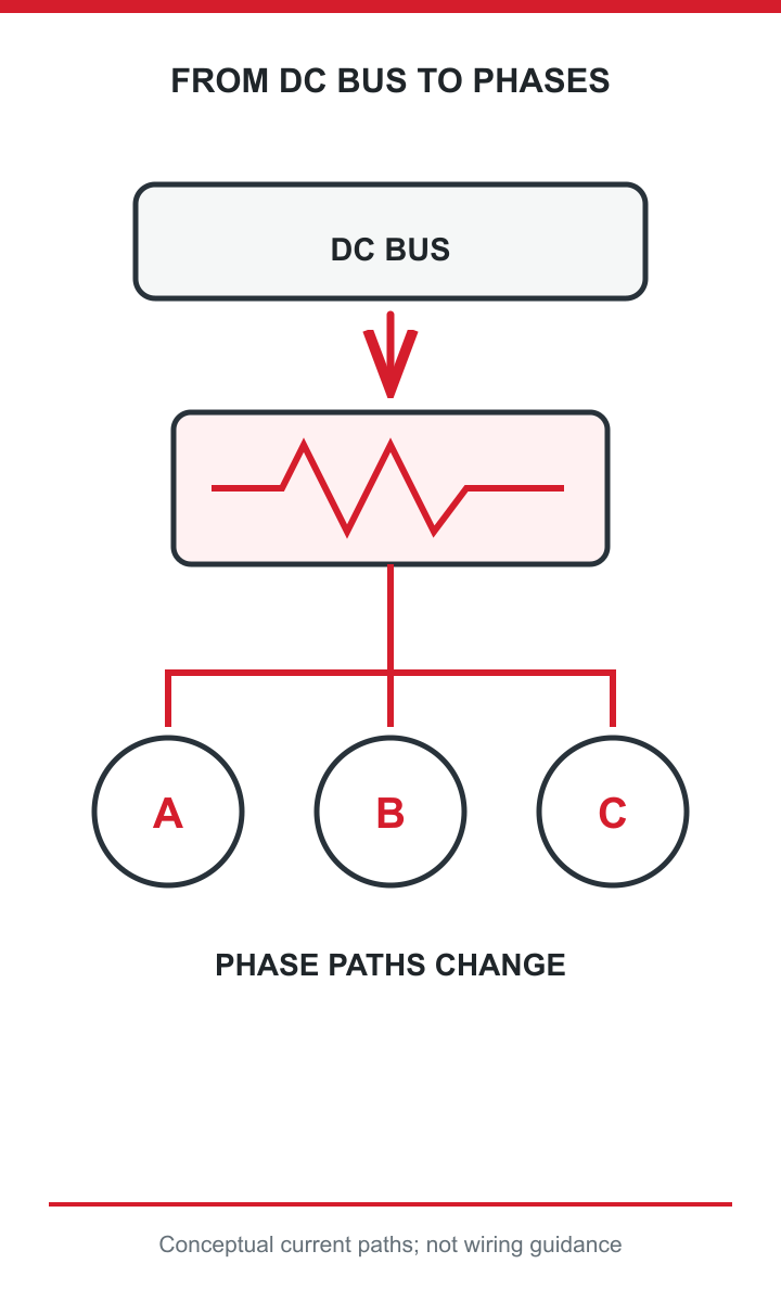
The drive changes phase current paths while using a DC bus.
| Layer | What you identify | Why it matters |
|---|---|---|
| Supply to the drive | The input specified for the complete controller or integrated assembly | This determines what source the equipment may accept. |
| Drive electronics | The circuit that switches power according to rotor position and control commands | This replaces mechanical commutation; a bare motor normally needs a matched drive. |
| Motor phases | The separately energised stator windings | Their changing currents create rotation; they are not an invitation to apply mains power directly. |
For example, a battery-powered machine can provide DC to a controller. The controller does not simply pass that DC unchanged to one pair of motor terminals; it switches the phase currents as the rotor moves. A viewer who measures or diagrams those phase currents may call them “AC-like”. Another viewer looking at the drive’s input will call the system DC-powered. Both may be describing a different point in the same assembly.
That distinction is the answer to the apparent paradox. It also explains why selecting a motor by supply label alone is inadequate: the controller, feedback arrangement and permitted operating conditions remain part of the decision.
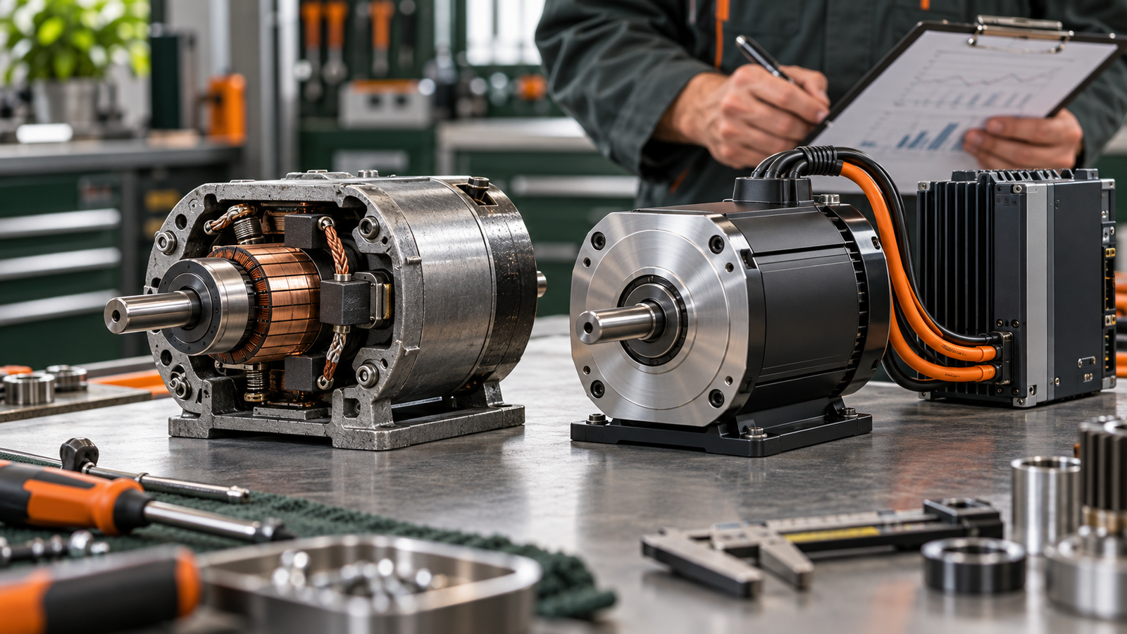
The labels “brushed DC”, “brushless DC” and “AC induction” group motors by more than the shape of a supply waveform. A brushed DC motor uses physical brush contact and a commutator. In a BLDC motor, the rotor is a permanent magnet and electronic switching changes current in stationary windings. An induction motor develops rotor currents through induction rather than using the same permanent-magnet rotor arrangement. These differences change the drive and control requirements.
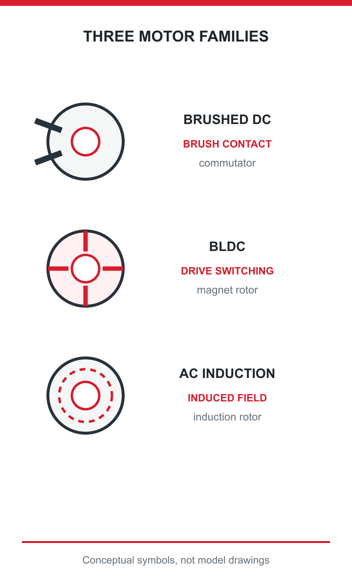
The three motor families differ in how they operate.
It is therefore misleading to reason, “the BLDC phases see changing current, so the motor must be an AC induction motor.” A controller can create changing phase currents from a DC link, while the machine remains a BLDC design. Conversely, an AC-powered product might rectify incoming power within an integrated drive before controlling its motor. The input connection of the packaged product, not the broad motor category, tells you what source is allowed.
Oriental Motor’s comparison of AC, brushless and brushed motors reflects this need to compare the full operating system rather than one word in the name. For a purchasing or integration decision, ask what rotor and commutation arrangement is used, which drive is supplied or recommended, and what the documented input is for that drive. Do not substitute a controller intended for another motor type just because connector count or nominal voltage looks similar. The naming question helps establish the concept; the model-level documents decide compatibility.
Start with the exact motor and controller model numbers. A generic product-family description may explain the principle but cannot authorise a particular connection. Use the current manufacturer datasheet, drive manual and product label for the assembly you actually have.
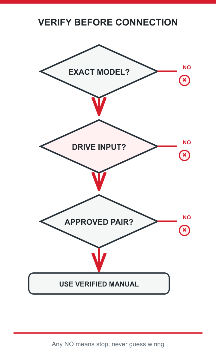
Verify model, drive input and pairing before connection.
This is a specification checklist, not a wiring procedure. Wiring, protection and commissioning must follow the verified product documentation and appropriately qualified practice. It turns the AC-versus-DC question into the information needed to make a reliable decision.
A useful enquiry to TENCH describes the machine’s available supply and the job the motor must perform, not merely “I need a brushless motor.” Its approved discovery information identifies voltage, power, speed, torque, load, duty cycle, temperature rise, environment and control method as selection inputs. Those are the details needed to discuss a motor and controller together. They do not, by themselves, establish the electrical rating of a particular TENCH model.
For example, an equipment designer might know the available DC bus and required shaft speed but still need to state the peak load, continuous load and operating cycle. Without those, a nominal power figure can hide the real application demand. Similarly, saying “AC supply available” is incomplete unless the permitted input of the proposed controller or integrated assembly is known. The relevant product datasheet must settle that point.
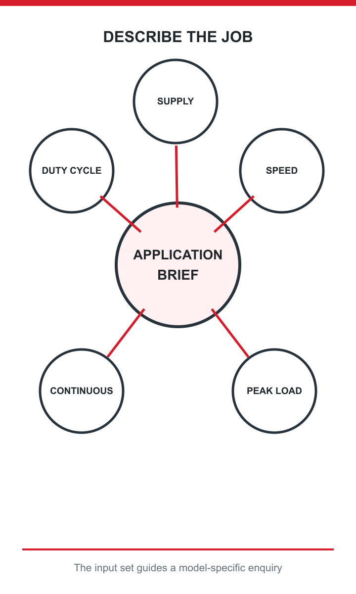
Supply, speed, load and duty define the motor-drive enquiry.
TENCH can use the selection inputs in its customer discovery process to discuss an appropriate brushless motor-and-controller combination. The value to the reader is a clearer requirements exchange: fewer assumptions about the power source, explicit operating conditions and a model-specific compatibility check before purchase or installation. Share your available supply, required speed and torque, load and duty cycle when requesting that check. This is an invitation to verify a candidate solution, not a claim that every TENCH motor accepts the same supply.
The most consequential error is to treat the phrase “brushless DC” as a wiring instruction. A BLDC motor generally depends on an electronic controller to energise its phases in the correct sequence. Connecting an arbitrary AC mains feed to bare motor leads is not justified by the fact that phase currents change during normal operation. Connecting a DC supply directly to those leads is not justified by the “DC” label either. The exact assembly documentation governs both cases.
For example, a purchaser may mistake a three-phase motor connector for an AC-mains input; the connector alone cannot establish permitted supply.
A second error is to ignore the boundary between the controller’s input and output. Suppose a product description mentions an AC-fed machine but a BLDC motor inside it. That can be perfectly coherent if the packaged electronics convert and control the incoming power. It does not follow that the bare motor itself is designed for direct AC input. Equally, a battery-fed BLDC system can contain switching waveforms at the motor without becoming an AC induction motor.
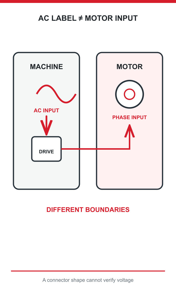
Machine input and motor phase input are different boundaries.
A third error is to choose by nameplate power alone. A motor and controller can share a plausible voltage or wattage while differing in feedback, allowable current, thermal duty or control method. The consequence is not just poor performance; it can be an inappropriate and potentially unsafe integration.
When an online answer seems to disagree with another, ask which layer it describes. Then check the exact datasheet and manual. This resolves most apparent contradictions without pretending that a broad motor category supplies model-specific ratings.
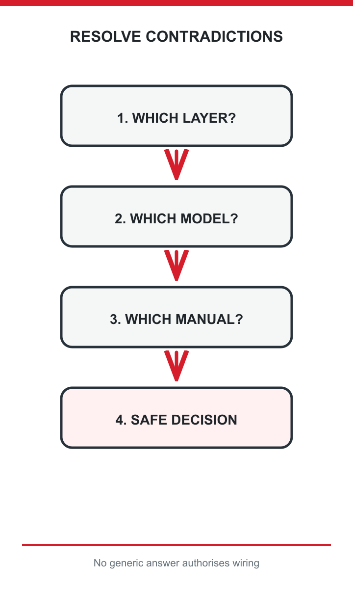
Resolve conflicting answers by checking the layer, model and manual.
Can a BLDC motor run straight from a DC battery? Usually not as a bare motor connected directly to two battery terminals. The system needs an appropriate electronic drive; confirm whether the product includes one and what input the manufacturer specifies.
Do changing phase currents make it an AC motor? They explain the confusing terminology, but they do not turn a permanent-magnet BLDC design into an AC induction motor. Distinguish the drive input from its switched outputs and the motor’s construction.
Are all brushless motors BLDC motors? No. “Brushless” only rules out a mechanical brush arrangement. Use the complete motor designation and documentation before choosing a controller or power source.
If you remember one safeguard, remember this: the answer to “are brushless motors AC or DC?” is a starting point for identifying the actual motor-and-drive system, not permission to connect power. For a BLDC design, expect electronically switched stator phases and a suitable controller; verify that controller’s specified input and the exact motor pairing. Questions about Hall sensors, PWM, back EMF and field-oriented control deserve their own treatment once the basic supply distinction is clear.



Leave a Reply