A BLDC servo drive is selected for an axis, not a motor label in isolation. The right unit must supply the motor within its electrical limits, interpret its feedback correctly, and execute the machine's intended control mode through a real duty cycle. A drive that spins a brushless motor on a bench may still be unable to position the load, hold it safely, manage returned energy, or communicate with the controller. Start with the motion profile and the exact motor and feedback identifiers. Compare the documented supply range, continuous and peak output current, supported feedback, command interface, protective behaviour, and environment rating. The final proof is a controlled test of the assembled axis.
This is a buying and engineering sequence, not a universal compatibility chart. Manufacturers use different rating conventions; identical headline wattages do not establish a match. The sections below turn a broad search for a BLDC servo drive into a specification a supplier can actually check. Where a model-specific answer is unavailable, record the unknown instead of substituting a confident guess.
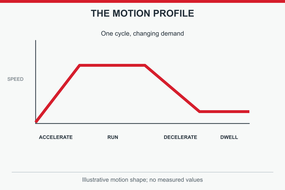
Describe the load before choosing electronics. What mass or inertia moves, through which transmission, over what distance and time? Record steady speed, acceleration, deceleration, reversals, dwell, and the fraction of a cycle spent in each state. State whether the axis must hold position against a load, regulate speed only, or follow an accurate position trajectory. A steady conveyor and an indexing table that starts and stops every second can make very different peak-current and thermal demands despite similar average power. One headline motor-power number cannot replace the motion profile.
Original conceptual diagram; read the adjacent paragraph for detail.
Record the available supply, cabinet temperature, cooling, cable length and installation constraints. The mechanism may impose reflected inertia, friction or occasional shock that a no-load motor catalogue cannot reveal. A useful first-pass specification gives continuous torque and speed, short-duration acceleration torque, operating cycle and worst expected load. If these are unknown, mark them for measurement rather than asking a supplier to approve guesses. Oriental Motor's BLDC-versus-servo comparison makes the application distinction explicit: speed regulation alone is not the same selection problem as a positioning servo axis.
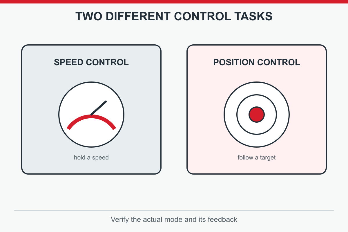
The words brushless drive and servo drive are not interchangeable guarantees. A BLDC speed controller may use Hall signals or estimated rotor position to regulate speed, sufficient for some fans, pumps or conveyors. A positioning servo must also close the appropriate feedback loops around commanded motion and handle tracking error, stopping and faults for the machine. Some units support several modes; others are built for one. Ask for the actual position, velocity and torque modes and which feedback each requires. Do not infer those functions from motor technology alone.
A simple driver may be cheaper and easier to commission where precise positioning is unnecessary. Conversely, a speed-only driver does not become a precision servo merely because an encoder is plugged into it. Confirm the machine controller's command format and the drive's supported operating mode together. FAULHABER describes feedback-based speed regulation and its own supported motor and sensor combinations. That is useful technical context, but not evidence that every speed controller can replace a full position-control drive.
Original conceptual diagram; read the adjacent paragraph for detail.
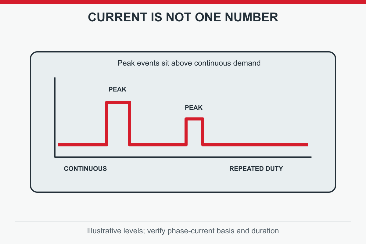
With machine demand defined, shortlist a motor that can produce the required torque across the speed range and complete the duty cycle within thermal limits. Then select a drive able to supply that motor under the same profile. Use the motor's torque constant and the manufacturer's current convention to translate torque demand into current where necessary. Compare normal demand with continuous drive output; compare acceleration or overload events with permitted peak output and its stated duration. A one-second peak allowance cannot be used repeatedly as though it were a continuous rating.
Look beyond the normal running point. Starting a heavy load, holding against gravity, stopping an overhauling load and reversing quickly can govern sizing. The control dynamics must also suit mechanical inertia and stiffness; more current does not cure a flexible coupling or poor encoder signal. ElectroCraft's selection workflow ties load, motor, electrical and environment questions together. Anaheim Automation likewise treats a BLDC motor and controller as a system. Use those as methods, then verify the exact shortlisted part numbers against current data sheets and application notes.
Write electrical checks as separate lines rather than one ambiguous amps figure. Input-supply range and DC-bus conditions belong on one line; motor phase-current ratings belong on another. Drive output may be specified as RMS or peak phase current, while a power supply may be rated in DC input current. Those quantities cannot be swapped. Ask the supplier to reconcile conventions for the named motor winding, drive model, voltage and switching method. Check nominal and maximum input voltage, expected supply variation, inrush, and any separate control supply. A suitable nominal voltage is not enough if regenerative or transient conditions can exceed a bus limit.
Original conceptual diagram; read the adjacent paragraph for detail.
Peak current also needs a duration, repetition rate and temperature assumption. Compare the axis's worst acceleration and deceleration with those limits, not a single front-page figure. Verify braking resistor or regenerative handling where the load returns energy to the bus, and determine how undervoltage and overcurrent faults are reported. FAULHABER's selection criteria explicitly call for voltage and current to match the motor, but its model-specific values must not be copied as another supplier's specifications. If data sheets use different definitions, obtain a written, model-specific clarification before approval.
| Check | Compare on the same basis | Decision |
|---|---|---|
| Supply voltage | Normal and worst-case bus range | Within both drive and motor limits |
| Continuous output | Phase-current convention and ambient rating | Sustains the real duty cycle |
| Peak output | Magnitude, allowed time and repetition | Covers each acceleration event |
| Returned energy | Deceleration and braking arrangement | Bus remains within documented limits |
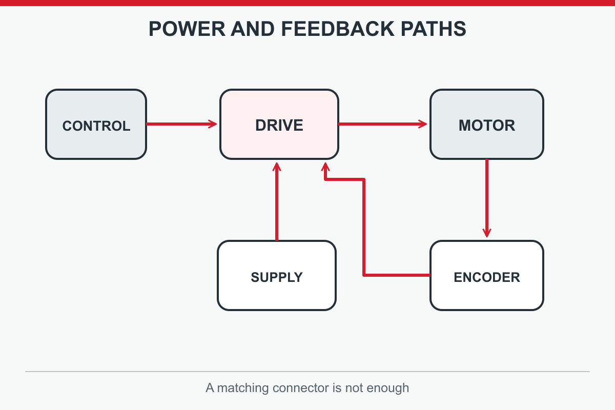
Feedback is part of motor-drive pairing, not a late accessory. Identify the fitted Hall sensors, incremental encoder, absolute encoder or other device by exact model and wiring. Check the drive's supported signal type, voltage, resolution, commutation method and input pinout. A physically fitting connector can carry the wrong signal. If an application needs repeatable absolute position at power-up, an incremental channel alone may require homing; if it needs only speed control, a simpler arrangement may suffice. The answer depends on the machine's operating and safety requirements.
Separate commutation feedback from process feedback when both exist. The sensor used to decide which phase to energise need not be the one measuring final load position. Cable length, shielding, grounding and routing beside power conductors can affect signal integrity. A valid catalogue match therefore names the motor winding, sensor option, drive firmware and cable arrangement. Elmo's selection material highlights matching feedback and control architecture; FAULHABER documents several different supported sensor combinations for its own controllers. Neither proves a third-party combination without exact interface documents.
Original conceptual diagram; read the adjacent paragraph for detail.
The drive must understand commands from the machine controller. List the requested mode, command source and update requirements: analogue reference, pulse and direction, a fieldbus, or another documented interface. Verify exact protocol version and I/O for enable, ready, fault reset, limits and brake. If a PLC expects one status word while a drive exposes another, an electrically sound axis can still fail integration. Commissioning software and parameter backup matter when identical machines must be replicated or serviced.
Treat protective functions separately from production control. Determine what happens after loss of feedback, overcurrent, overtemperature, bus undervoltage, network interruption and a commanded stop. Identify whether a safety-rated function is needed and verify its certification and wiring in the actual product documentation. A normal enable input is not automatically a safety function. The system designer should define a safe state and validate it under the applicable machine risk assessment. Ask a supplier to demonstrate the fault and stop sequence for the specific drive, not merely point to a feature list. This is particularly important for an axis carrying a vertical or otherwise hazardous load.
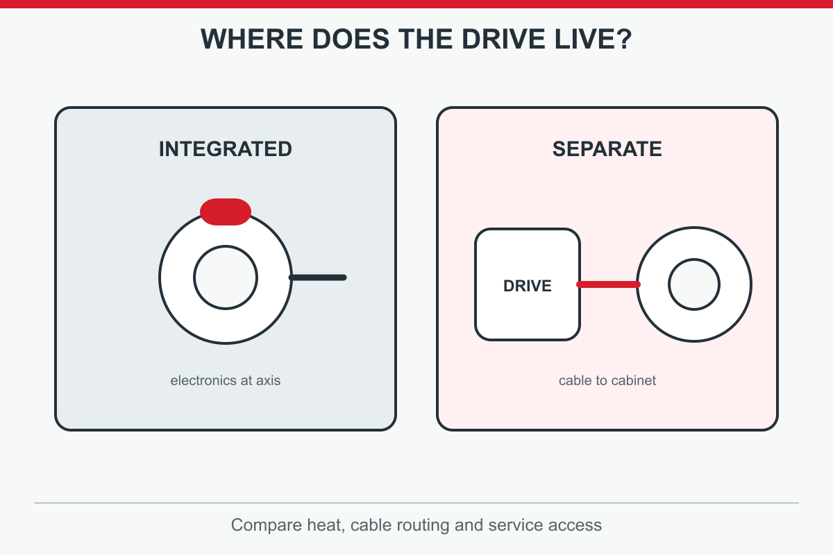
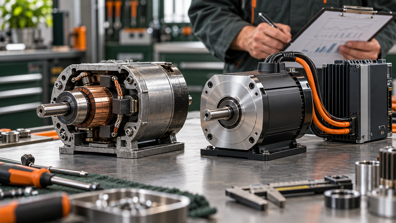
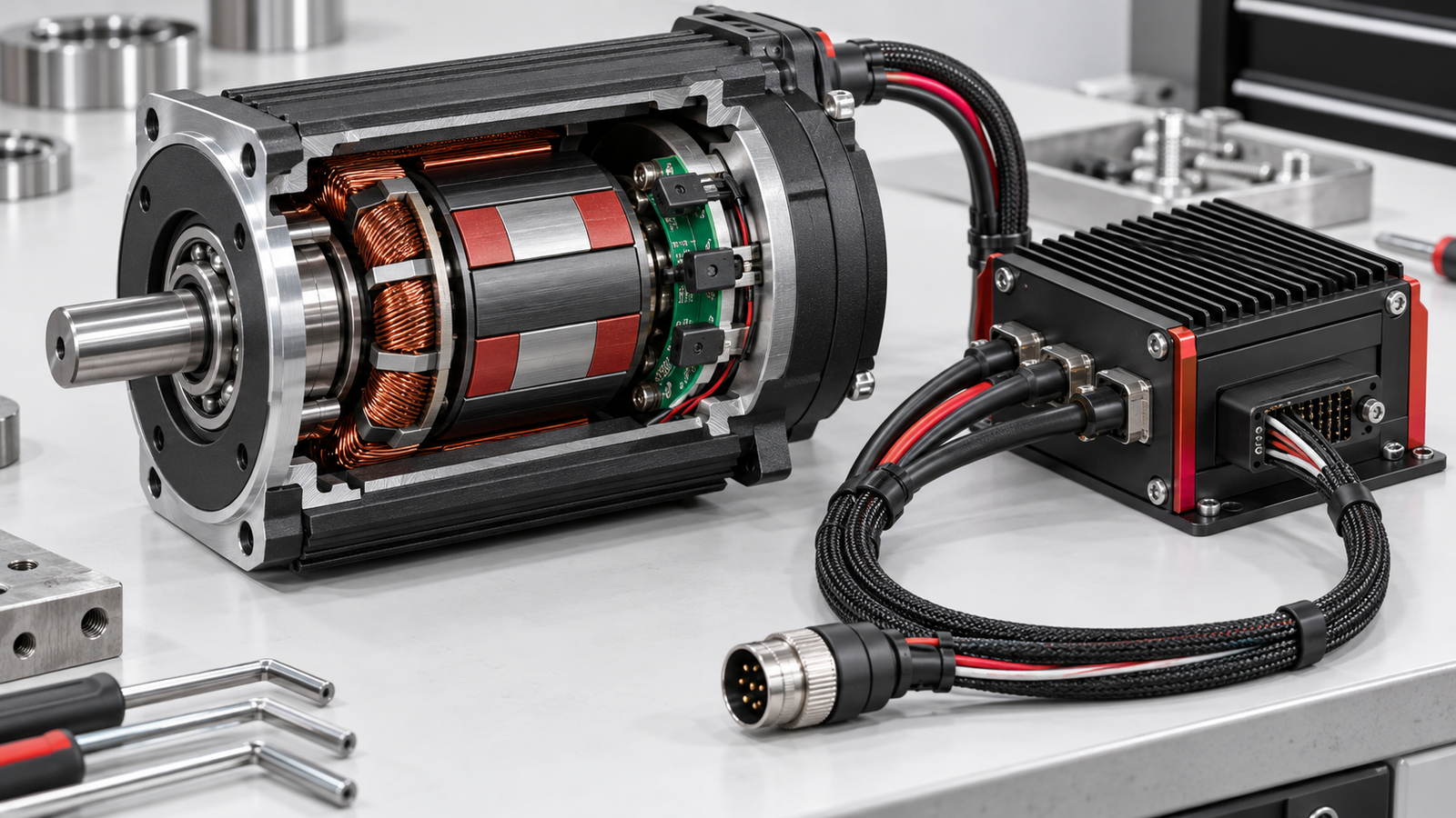
An integrated motor-and-drive assembly can simplify cabling and reduce cabinet space, but the electronics then share the motor's environment. Heat, vibration, cleaning, access for diagnostics and replacement procedure can matter more. A separate cabinet drive can be easier to isolate and service in some machines and keep electronics away from the moving load, but it requires a defined power and feedback cable installation. Neither architecture is universally better. Compare the installed system, including connectors, electromagnetic compatibility practice, protection and spare-part strategy.
Original conceptual diagram; read the adjacent paragraph for detail.
For a moving axis, cable routing and repeated flex may dominate reliability. For a compact fixed-axis machine, an integrated package can remove several wiring errors. Check whether an integrated option actually includes the required control mode, network and safety behaviour; the word integrated does not guarantee them. Conversely, a cabinet drive should not be chosen merely because another machine used one. Evaluate temperature at its location, permissible cable length, service access and replacement lead time alongside electrical performance. Document the choice so a future maintainer knows why that architecture fits this axis.
Give suppliers a coherent specification pack: the load and motion profile, motor model and winding, feedback device, available supply, controller interface, required modes, cable arrangement, environment and expected production cycle. Add the tolerance that matters to the user, such as positioning error, repeatability, speed regulation, settling time or throughput. For an existing machine, attach relevant alarms and a short trace. Mark unknowns honestly. This lets a supplier distinguish a supported configuration from a plausible but untested combination.
Ask for a response naming the proposed motor, drive, firmware, feedback option and cables. Request data-sheet references for continuous and peak ratings, overload duration, supported sensor type, control interface and protective response. Ask which calculations or tests remain the integrator's responsibility. A quote for a drive alone is not a completed axis design. If two candidates look close, compare verified limits under the same duty cycle rather than their front-page power number. Keep the approved specification revision and documented exceptions; they help when the machine changes or a replacement is required.
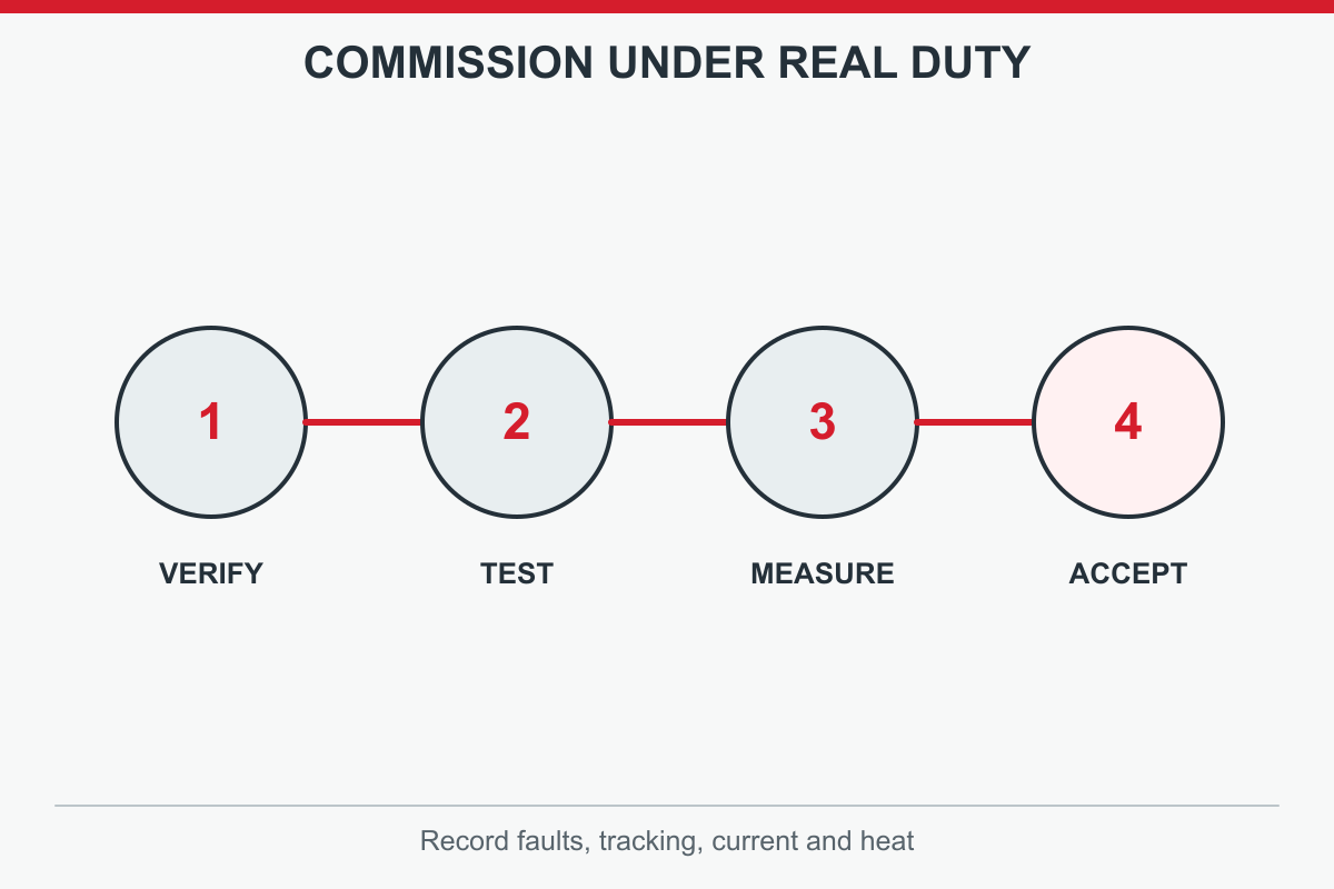
Commissioning must test the actual load and normal cycle, not only a free-spinning motor. Begin under the machine builder's safe procedure with limits and stop behaviour checked. Confirm motor direction, feedback sense, homing or absolute-position logic, command scaling and fault response before high-speed operation. Compare commanded and actual speed or position through acceleration, steady travel, stopping and reversal. Record current, tracking error and temperature after representative repeated cycles. A transient that looks harmless during one empty stroke can become a continuous overload in production.
Original conceptual diagram; read the adjacent paragraph for detail.
Make one documented change at a time during tuning and preserve a parameter backup. Check that a smoother trace does not hide unacceptable delay, overshoot or heat. Test the supply at expected operating limits if the equipment specification requires that range. Validate mechanical brakes and safety functions with the responsible team. The acceptance record should identify hardware and firmware revisions, load, ambient conditions and measurement method. That is evidence that the selected drive works in this machine, stronger than assuming compatibility from a product-family name.
Several shortcuts cause avoidable failures. Choosing solely by watts ignores speed-torque behaviour, overload duration and thermal duty. Choosing by peak amps without a time limit can leave a drive overheated in repetitive operation. Matching a connector shape without checking feedback type and pinout can prevent correct commutation. Treating any BLDC driver as a position servo may omit the required control loop. Treating ordinary enable as a certified safe stop can create a safety gap. Each shortcut removes a different piece of the same system-level specification.
Copying a successful pairing from another axis is also risky. A changed gearbox, heavier payload, longer cable or different controller interface can invalidate the comparison. Vendor examples illustrate methods, not universal settings. If a supplier cannot identify the supported motor and sensor option, obtain the missing model documents before commissioning. If regeneration, braking or environmental derating matters but remains undocumented, record an unresolved design question. Rejecting an unsupported claim early is cheaper than discovering it after installation. A good review records why a candidate fits and what still needs a test.
TENCH publishes industrial DC servo motors, drivers and related motion-control products, so a model-specific discussion can help an OEM specifying a new axis or replacing a documented component. That does not imply every TENCH motor works with every TENCH drive or that an unknown third-party encoder and controller are supported. A useful enquiry names exact motor and drive candidates, supply, load cycle, required speed and torque, feedback option, communication method and environment. For a replacement, add original system identifiers, firmware and fault history.
Original conceptual diagram; read the adjacent paragraph for detail.
Ask TENCH to confirm what current documentation supports for those named parts and what remains for the machine integrator to calculate or validate. A customer may need a matched kit, particular feedback interface or different controller mode; the answer must come from a data sheet and application review, not this general article. Where the system includes a third-party gearbox, safety controller or unusual load, state it explicitly. The next step is a scoped technical exchange, not a promise of automatic compatibility or guaranteed production performance.
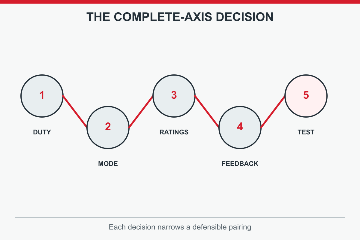
Select a BLDC servo drive in this order: define load and motion cycle; decide whether the axis needs speed regulation or positioning; identify the exact motor winding and feedback; match supply and continuous and peak phase-current ratings under the same conventions; verify commands, faults and safety behaviour; then test the assembled axis under representative duty. Record part numbers, firmware, wiring and acceptance data. If any item remains unavailable, mark selection provisional instead of treating a plausible catalogue pairing as approved.
The central distinction is simple: drive, motor, sensor, controller and mechanics form one controlled system. A speed controller may be right for a speed-only task, while a full servo drive can be essential for precise positioning. Neither should be chosen from the word brushless alone. Use manufacturer documents for the exact shortlisted combination and involve the machine builder in safety and commissioning decisions. A complete specification pack gives a supplier a useful question to answer and your team a repeatable basis for approval, service and later replacement.



Leave a Reply