

Author: Verna Lyu
Technical reviewer: Wen Liu, Engineer
This guide was checked against current TENCH product specifications and the motor-selection references listed at the end. Family-level values are used only for screening; the final choice must be made from one model row and verified in the intended machine.
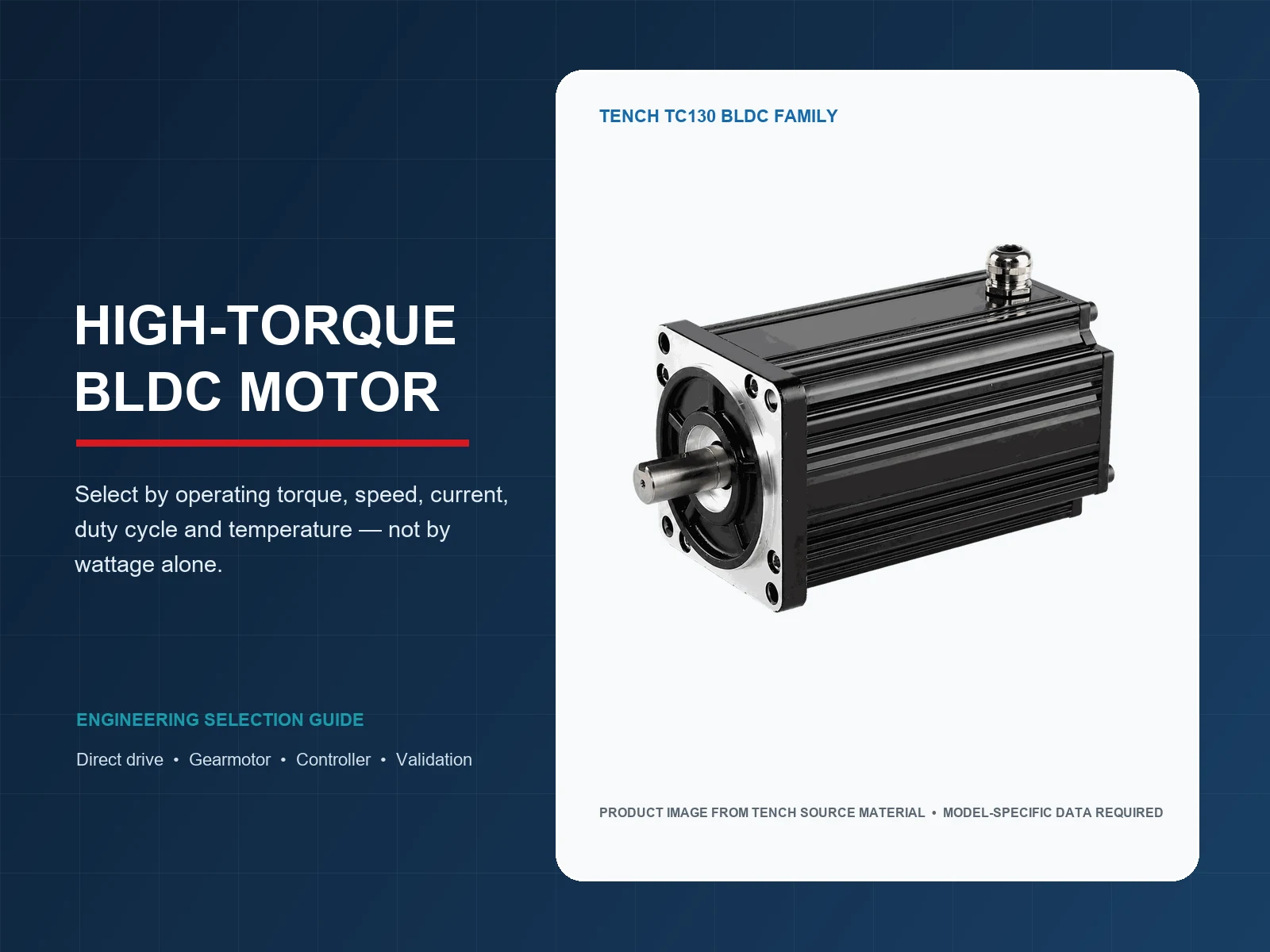
A high torque brushless DC motor should be selected at a defined torque and speed, for a defined time and temperature. Start with the load's continuous torque, peak torque and duration, loaded speed, acceleration, duty cycle, supply limits, available space and environment. Then check whether a direct-drive motor or a motor-plus-gearbox system can meet those points without exceeding the motor, controller or transmission ratings.
Motor wattage alone is not enough. Torque is closely related to motor current, while voltage provides the headroom needed to overcome back EMF at speed. Continuous torque is normally a thermal limit; peak torque is a short-duration capability; stall torque is not a continuous operating point. A controller current limit, inadequate cooling or an undersized gearbox can reduce usable torque even when the motor nameplate appears large enough.
High Torque Is an Operating Requirement, Not a Standard Motor Class
The phrase high-torque BLDC motor has no universal threshold. A compact actuator may need a few tenths of a newton-metre, while a larger industrial mechanism may need tens of newton-metres. The same torque can also describe very different power levels at 100 rpm and 3,000 rpm. A useful requirement therefore includes torque, speed and time at the same operating point.
Begin at the machine shaft. Record the normal running torque, the highest process torque, acceleration and deceleration torque, static friction, gravity or spring load, external disturbances and any holding requirement. Add the required speed range, reversal pattern, starts per hour and ambient conditions. If the load data are uncertain, measure the existing machine or build a conservative load model before choosing a motor.
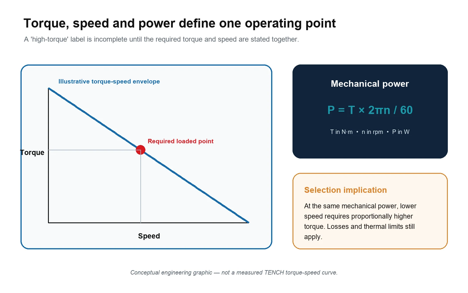
This relationship is a useful consistency check. At the same mechanical power, reducing speed by a factor of ten requires approximately ten times the torque before losses are considered. It does not size the motor by itself because it says nothing about acceleration, current, thermal limits, efficiency, controller capacity or the gearbox's permissible torque.
Separate Continuous, Peak and Stall Torque
| Torque term | What it should mean | Selection use | What must be verified |
|---|---|---|---|
| Rated or continuous torque | Torque available continuously under stated voltage, speed, ambient and cooling conditions | Normal running and the thermal baseline | Exact operating point, mounting, cooling, ambient temperature and allowable temperature rise |
| Peak or intermittent torque | Higher torque allowed for a limited time | Acceleration, breakaway and short process disturbances | Magnitude, duration, repetition rate, starting temperature, controller current and mechanical limits |
| Starting torque | Torque available from zero speed under the chosen control method | Loaded start and overcoming static friction | Hall/encoder/sensorless strategy, current limit, rotor position and supply sag |
| Stall or locked-rotor torque | Torque at zero speed under a stated test condition | A boundary or fault reference, not a running rating | Whether the value is calculated or tested, permitted time and stall protection |
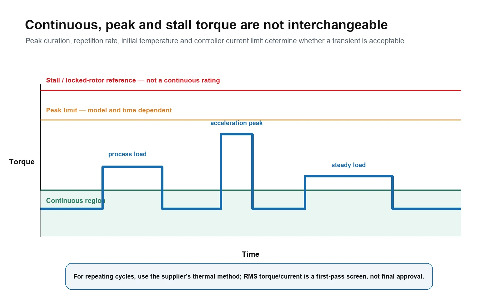
Continuous torque is normally constrained by temperature. Copper loss increases approximately with the square of current, while iron, switching and mechanical losses also change with speed and control method. A motor that survives a short acceleration pulse may overheat when asked to repeat that pulse too often or to hold the same torque continuously.
Peak torque is incomplete without time. Portescap's thermal guidance explains that a short peak can exceed continuous current while the winding remains below its maximum temperature, and that a repeated cycle may be screened with an RMS current or torque calculation when the cycle is short relative to the thermal time constant. That is a first-pass thermal model. The exact motor, mounting and cooling still need to be validated.
Do not use stall torque as a substitute for peak torque. At zero speed there is no mechanical output power, back EMF is minimal, and winding heating can rise rapidly. The controller should limit current and detect a failed start or locked rotor within the permitted time.
Understand How Current, Torque Constant, Voltage and Speed Interact
Current and torque
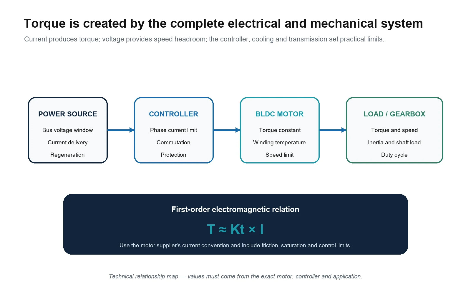
For a first-order motor model, electromagnetic torque is proportional to the torque-producing current: T ≈ Kt × I. The torque constant Kt is commonly expressed in N·m/A. In a real system, the usable shaft torque also depends on no-load losses, magnetic saturation, commutation, current regulation and temperature. Manufacturers may publish phase RMS current, phase peak current or DC-bus current, so two ampere values cannot be compared until their definitions match.
The controller therefore sets a practical torque ceiling. It must support the continuous phase current required by the duty and the peak current required by acceleration or disturbance loads for the necessary time. A larger motor cannot produce its expected torque if the controller, battery, power supply, cable, connector or fuse limits the current first.
Voltage and speed
Voltage does not independently guarantee more torque. As motor speed rises, back EMF rises, so the controller needs sufficient DC-bus voltage to force the required current through the winding at the target speed. A low bus voltage may allow strong current at low speed but prevent the motor from reaching the required loaded speed. Conversely, a higher voltage does not authorize more current than the motor and controller can safely carry.
Specify the minimum, nominal and maximum bus voltage at the controller terminals. Include battery state of charge, power-supply tolerance, cable drop, startup sag and regenerative rise during deceleration. Confirm the winding, maximum speed and controller voltage range for the exact model rather than matching only a 24 V or 48 V label.
Decide Between Direct Drive and a Gearmotor
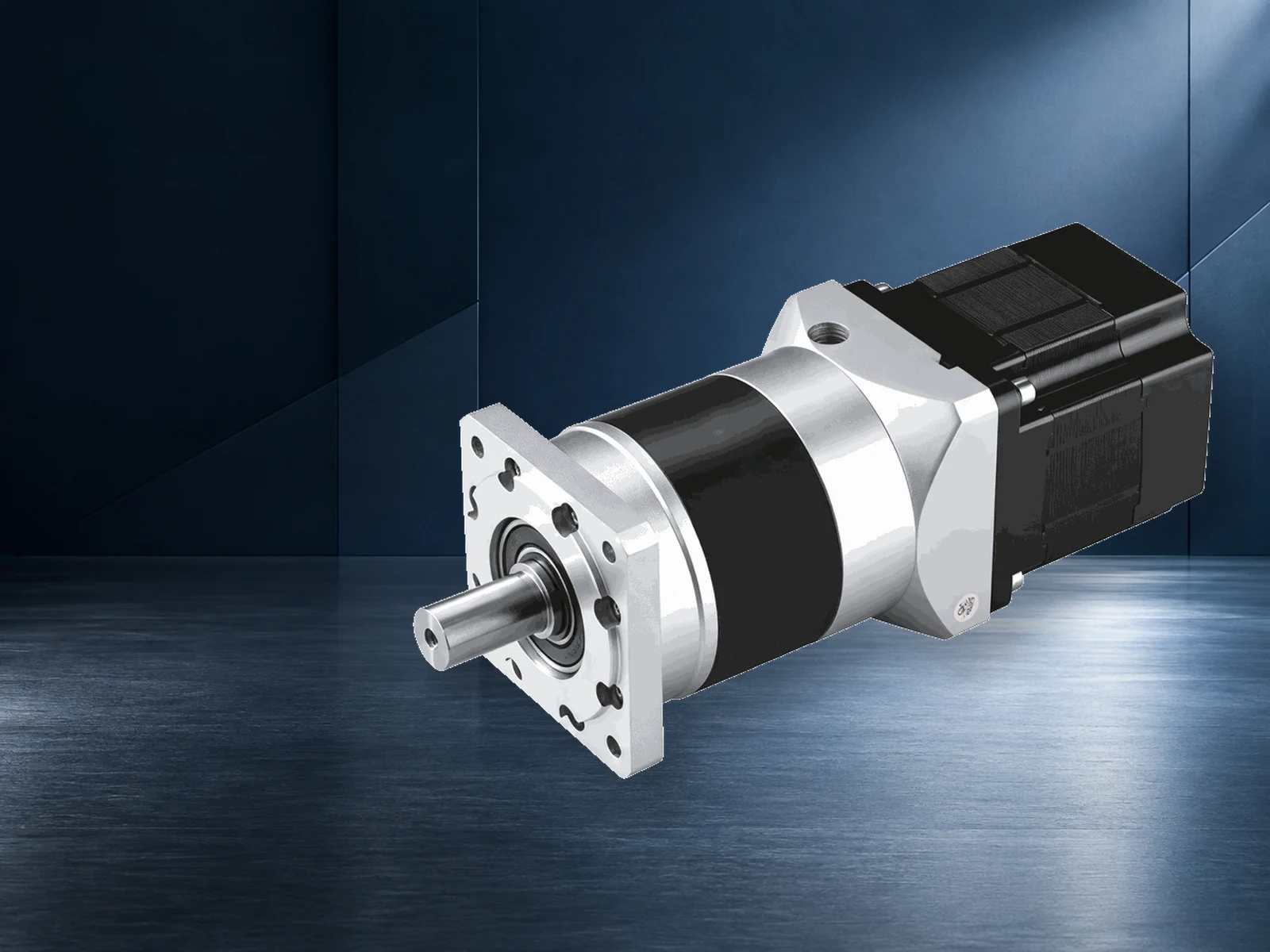
A low-speed, high-torque output does not automatically require a physically large direct-drive BLDC motor. A gearbox allows a motor to run at a more practical speed while multiplying output torque. The first-order estimate is output torque = motor torque × reduction ratio × gearbox efficiency. Actual selection must remain below the gearbox's published continuous and intermittent torque, speed, radial load, axial load and inertia limits.
Direct drive removes gear-mesh losses and backlash and may reduce mechanical noise and maintenance. It can be the right architecture when positioning quality, reversibility, low acoustic noise or mechanical simplicity outweigh size and current. The trade-off is that the motor must produce the load torque directly, which can increase frame size, current and thermal demand.
A gearmotor is often more compact at the load when the output speed is much lower than the motor's efficient operating range. It also introduces ratio error, efficiency loss, backlash, torsional compliance, noise, wear and output-shaft limits. A high ratio does not create unlimited torque: the gearbox rating can become the system limit before the motor reaches peak torque.
| Decision point | Direct-drive BLDC | BLDC gearmotor |
|---|---|---|
| Low output speed | Possible with suitable feedback, control and thermal design | Often practical because the motor can run faster |
| Output torque | Produced directly by the motor | Multiplied by ratio and reduced by gearbox losses |
| Backlash | No gearbox backlash | Depends on gearbox type, ratio, wear and preload |
| Mechanical limits | Motor shaft, bearings and mounting | Motor plus gearbox torque, speed, inertia and shaft-load limits |
| Holding at zero speed | Requires current or a separate brake unless another mechanism holds | May still require a brake; do not assume a gearbox is self-locking |
| Validation focus | Low-speed control, current, temperature and mounting stiffness | All direct-drive checks plus gearbox temperature, backlash, noise and shaft loads |
Worked Example for a Low Speed Load
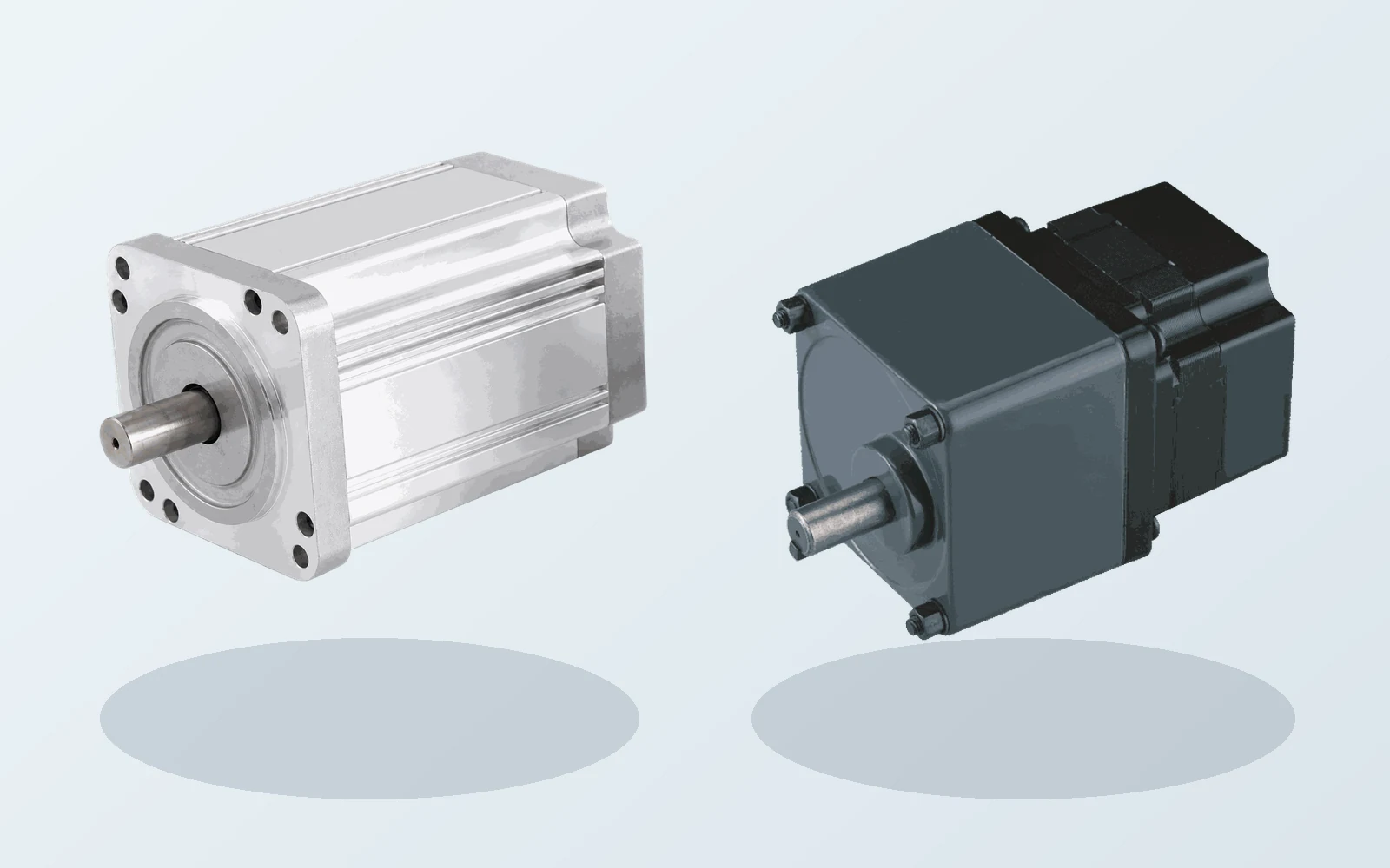
Consider an illustrative load that needs 8 N·m continuously at 120 rpm and 15 N·m for one second in every ten-second cycle. If the first-pass architecture uses a 10:1 gearbox and an assumed efficiency of 85%, the motor would run near 1,200 rpm. The estimated motor-shaft requirements are 0.94 N·m continuously and 1.76 N·m during the peak. The continuous load power is about 101 W, while the motor must supply about 118 W of mechanical power before other system losses are added.
| Screening item | First-pass result | Still to verify |
|---|---|---|
| Continuous load point | 8 N·m at 120 rpm | Measured load, friction and operating margin |
| Motor point through 10:1 gearing | 0.94 N·m at about 1,200 rpm | Exact ratio, efficiency map and motor torque-speed curve |
| One-second peak | 1.76 N·m at the motor shaft | Motor peak duration, controller current and gearbox intermittent rating |
| Repeated-cycle thermal screen | About 1.05 N·m RMS at the motor shaft | Supplier thermal model, mounting, ambient and stabilized test |
This calculation is a screening example, not a TENCH model recommendation. The gearbox must carry both 8 N·m continuous and 15 N·m peak at the output, and the motor-controller pair must meet the calculated shaft points with the correct current convention. Use How to Size a BLDC Gearmotor for the full load-side calculation.
Check Low-Speed Torque, Feedback and Holding Duty
A BLDC motor can produce torque at low speed, but low-speed performance is not guaranteed by the motor name. Basic back-EMF sensorless control has little rotor-position information at standstill and low speed. A loaded start, frequent reversal or very low stable speed often needs Hall feedback, an encoder or a controller with a validated low-speed estimation method.
Cooling may also change at low speed. A self-ventilated assembly moves less air, and a compact enclosure may trap heat. Holding torque at zero speed can be especially demanding because current produces copper loss while the shaft does no mechanical work. For a vertical axis or safety-related load, define whether a mechanical brake, counterbalance or other holding device is required; drive torque alone should not be treated as a safety function without a suitable risk assessment.
If speed regulation, torque smoothness or position accuracy matters, state a measurable requirement. Examples include minimum stable rpm, allowed speed ripple, settling time, repeatability and acceptable acoustic or vibration level. The motor, feedback and controller must then be tested together against those limits.
See How Does a BLDC Motor Work? for the commutation and feedback principles behind this behavior.
Use the Controller and Power Source as Part of the Torque Specification
The motor's rated and peak torque can be reached only when the controller delivers the required phase current with the correct commutation or vector control. Confirm the supported motor type, pole-pair count, electrical-frequency limit, Hall or encoder interface, current definitions, continuous current, overload current and duration, switching strategy, protection thresholds and cooling conditions.
The power source must supply the corresponding DC-bus current without excessive voltage drop or nuisance shutdown. Include connector and cable heating, fuse and contactor ratings, battery internal resistance, supply overload behavior and the energy path during deceleration. A system may have enough motoring torque yet trip on overvoltage when an inertial or overhauling load returns energy to the bus.
Use the TENCH BLDC motor controller selection guide when the controller is not fixed. It separates bus voltage, phase current, feedback, control interface, regeneration, protection and thermal checks so a nominal wattage match is not mistaken for compatibility.
Screen the Thermal and Environmental Conditions
Published torque ratings belong to stated test conditions. Ambient temperature, altitude, mounting plate, enclosure, airflow, neighboring heat sources and repeated starts can change the available thermal margin. A winding may be much hotter than the external housing, and a short bench run may not reveal the stabilized temperature of the final machine.
For continuous duty, run the representative load until temperatures stabilize or until the validated thermal model says the worst point has been reached. For intermittent duty, start from the hottest credible condition and repeat the complete cycle. Monitor the motor, controller and gearbox where used. Apply the model-specific temperature limits and derating instructions; do not copy a generic housing-temperature threshold from another motor family.
Also define ingress protection, dust, moisture, chemicals, vibration, shock, cable movement and permissible surface temperature. A higher IP configuration can reduce heat transfer, while forced air or a conductive mounting surface can improve it. These effects must be included in the chosen model's rating or confirmed by test.
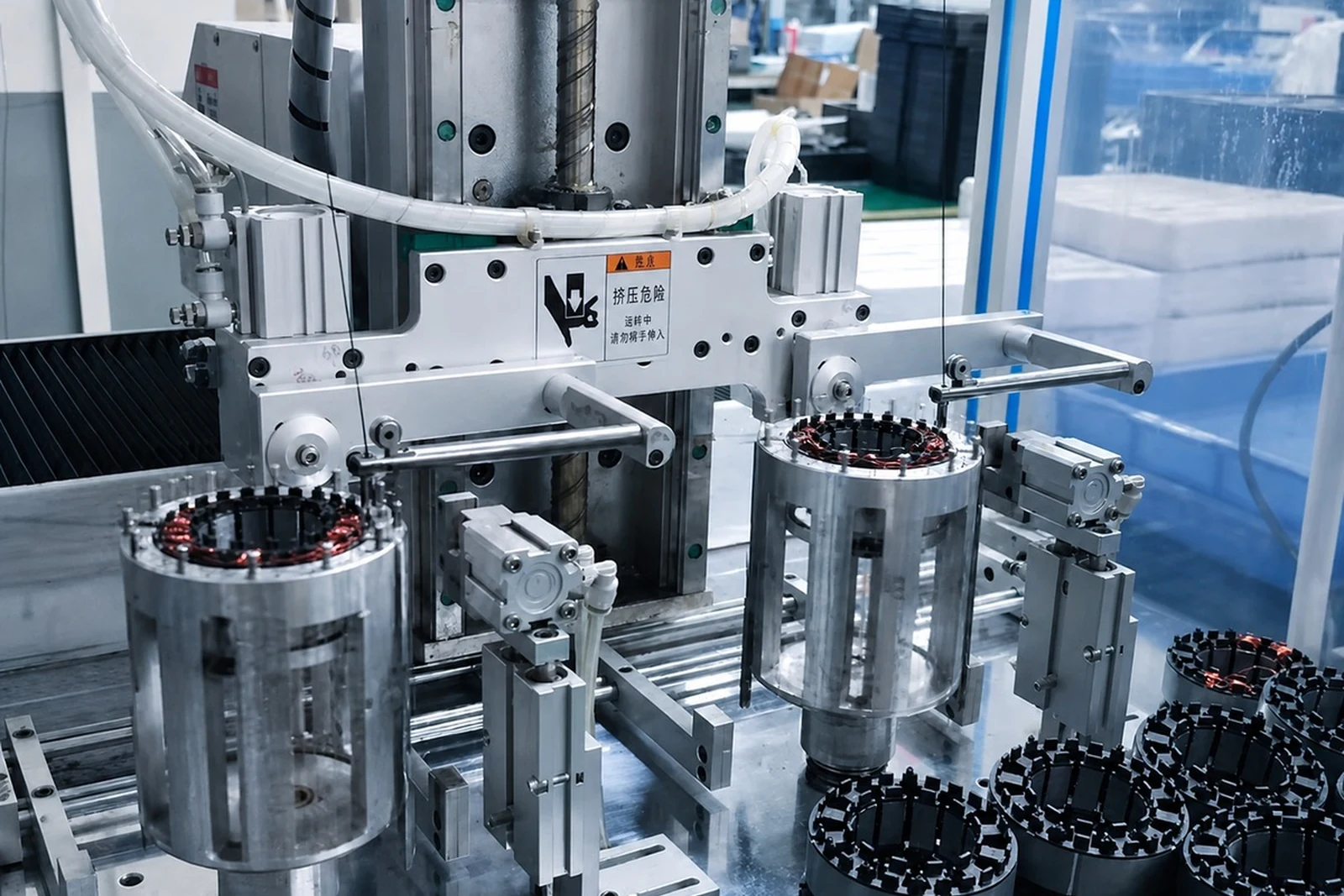
A Practical Eight-Step High-Torque BLDC Motor Selection Process
- Define the load-side operating points: continuous torque, peak torque and duration, speed range, acceleration, inertia, reversals, holding and duty cycle.
- Calculate mechanical power at each important torque-speed point and check that the requirements are internally consistent.
- Choose a direct-drive or geared architecture from output speed, torque, space, backlash, noise, shaft loads and service requirements.
- Shortlist motor windings and frame sizes using the exact torque-speed data, continuous rating, peak limit, maximum speed and mechanical envelope.
- Calculate the required motor and controller current using the supplier's torque constant and current convention; include supply sag and cable losses.
- Select feedback and control for loaded starting, minimum speed, torque smoothness, speed regulation, positioning and restart behavior.
- Check thermal and environmental limits for the real mounting, enclosure, ambient, airflow and cycle; include gearbox and controller temperatures.
- Validate the selected motor-drive-transmission combination in representative equipment before approving production.
How Current TENCH BLDC Families Fit the Screening Stage
TENCH publishes several high-power BLDC families across different frame, voltage, speed and torque ranges. The table below is a family-level starting point. Each 'up to' value belongs to a specific listed model and operating point; values from different rows must not be combined into a new rating.
| Published TENCH family | Published rated power | Published rated speed | Published torque range summary | Best use in screening |
|---|---|---|---|---|
| TC57BLD, 57 mm | 50–200 W | 1,000–3,000 rpm | Rated torque up to 0.64 N·m; peak up to 1.91 N·m | Compact industrial motor shortlist where space and moderate torque matter |
| TC80, 80 mm | 150–1,200 W | Standard models 1,500–3,000 rpm; listed high-speed models up to 20,000 rpm | Rated torque up to 3.2 N·m; peak up to 9.5 N·m | Broad mid-power range; choose the exact standard- or high-speed model row |
| TC130, 130 mm | 1.5–6.0 kW | 1,500–3,000 rpm | Rated torque up to 19.1 N·m; peak up to 40 N·m | Higher-power industrial shortlist where the larger frame and supply fit |

The TC57, TC80 and TC130 pages also list multiple voltages and model rows. Use the exact row that provides the required torque at the required speed. Then match its current, feedback and winding to a controller. If the required output speed is substantially below the motor's practical range, review the TENCH brushless DC gear motor category rather than forcing a motor-only choice.
For a wider model shortlist, compare the TENCH high-power BLDC motor category with the geared range, then return to the operating-point checks in this guide.
Validate the Shortlist Under the Real Duty Cycle
Use the calculation to build a shortlist, then approve the combination only after testing. The test plan should cover the worst credible load, ambient temperature, supply voltage and motion cycle. Include cold start, hot restart, minimum bus voltage, maximum speed, repeated acceleration, steady load, rapid deceleration, reversal, jam response and any holding period.
Record the DC-bus voltage and current, motor phase current when the equipment permits it, speed, output torque or a calibrated load proxy, motor and controller temperature, gearbox temperature, vibration, noise and fault history. Keep the controller parameters, firmware, motor model and winding code with the test record so the validated system can be reproduced.
Write the pass criteria before the test. Examples include completing every loaded start, staying within the model-specific current and temperature limits, reaching the required speed at minimum supply voltage, stopping without bus overvoltage, and remaining within the machine's noise and vibration limits. A failed test may require a different winding, ratio, controller, cooling method, acceleration profile or mechanical design. A higher wattage label alone may not solve the problem.
Information to Send a BLDC Motor Supplier
- Continuous torque, peak torque, peak duration and repetition rate at the load.
- Minimum, normal and maximum loaded speed, plus acceleration and deceleration time.
- Load inertia, friction, gravity or spring loads, reversals, starts per hour and holding requirement.
- Available DC-bus voltage range, current limit, power-source type and regenerative-energy constraints.
- Direct-drive or gearbox preference, allowed ratio, backlash, noise, radial load and axial load.
- Mounting, shaft, overall envelope, mass limit and cable or connector requirements.
- Hall, encoder or sensorless preference; speed, torque or position-control objective; PLC or communication interface.
- Ambient temperature, enclosure, airflow, IP requirement, dust, moisture, shock and vibration.
- Prototype quantity, annual volume, validation schedule and required compliance documents.
Frequently Asked Questions
Does a higher-wattage BLDC motor always provide more torque?
No. Power connects torque and speed. A higher power rating can come from higher torque, higher speed or both. Compare the exact rated and peak torque at the required speed, along with current and thermal limits.
Does increasing voltage increase BLDC motor torque?
Not by itself. Torque is primarily related to torque-producing current and torque constant. Voltage provides the headroom needed to maintain current as back EMF rises with speed. The motor winding, controller and current limits must all match the selected bus voltage.
Can I use stall torque as the required peak torque?
No. Stall torque is a zero-speed boundary under a stated test condition and produces rapid heating. Use the motor's documented peak torque, permitted duration and repetition conditions, then verify controller current and stall protection.
Is a gearbox always the best way to obtain high torque?
No. A gearbox is often practical for low-speed, high-torque output, but it adds loss, backlash, noise, wear and mechanical limits. Direct drive may be preferable when smoothness, reversibility or low backlash matters enough to justify a larger motor and higher current.
Can a BLDC motor deliver full torque at zero speed?
Some motor-controller systems can command torque at zero speed, but continuous holding is limited by current, winding temperature, controller capability and the machine's safety requirements. Loaded starting and holding behavior must be confirmed for the exact system; a mechanical brake may still be required.
What is the most important data for a high-torque BLDC motor enquiry?
Send continuous and peak torque with duration, loaded speed range, duty cycle, supply voltage range, controller and feedback needs, direct-drive or gearbox constraints, mounting and environment. Those values allow a supplier to evaluate an operating point instead of guessing from wattage.
Select the Operating Point, Then Select the Motor
Start with the operating point rather than the largest torque number in a catalogue. The selected motor-drive system must produce the required torque at the required speed for the required time, stay within current and temperature limits, and fit the mechanical and environmental constraints. Either direct drive or a geared drive can work when its trade-offs match the machine.
For an OEM review, send TENCH the load torque and speed points, motion cycle, supply, feedback, controller interface, mounting, environment and expected quantity through the engineering enquiry form. TENCH can then compare the relevant motor, controller and gearbox families and identify the model data that still need to be confirmed by prototype testing.
Technical References
- Portescap, Thermal Considerations for Ironless Brush DC and Brushless DC Motors.
- Portescap, Brushless DC Motors — specification definitions.
- maxon, Key Information: Motor Data and Operating Ranges.
- Oriental Motor, Speed Control Motor Systems Overview.
- Oriental Motor, Selection Calculations.
- TENCH, TC57BLD 57 mm Brushless DC Motor.
- TENCH, TC80 80 mm Brushless DC Motor.
- TENCH, TC130 130 mm High-Power Brushless DC Motor.

Leave a Reply