A BLDC motor pump is not a motor with a pipe attached. It is a hydraulic assembly, a brushless motor and an electronic drive selected to work together at a defined operating point. If you are choosing one for an OEM product, start with the liquid, required flow and total head; only then choose the motor and controller. A large maximum-flow figure cannot tell you what the pump will deliver against your system resistance. Equally, a motor's rated wattage cannot prove that the impeller, housing or seal is right for the fluid. This guide separates those decisions so a supplier can answer a meaningful specification rather than guess from a headline size. It explains how to read a pump curve, translate the hydraulic duty into an electrical duty, examine thermal and protection requirements, and define the boundary between a motor supplier and a complete pump manufacturer. The result should be a testable candidate at your actual duty point, not a universal promise about efficiency or service life.
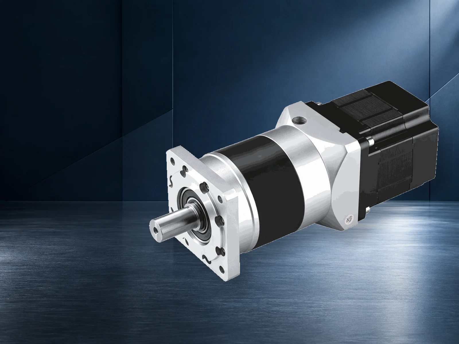
In a typical BLDC-driven pump, an electronic controller energises the motor windings in sequence. The motor turns an impeller or another pumping element; the hydraulic end moves liquid through the connected system. Some products integrate the motor, drive and wet end in one package. Others use a separate drive or a motor supplied to a pump designer. Both can be described casually as a BLDC motor pump, but their purchasing and validation responsibilities differ. Ask what is actually included: motor, controller, pump head, seals, sensors, cables and protection functions. A bare motor data sheet describes electrical and mechanical capability, not a complete flow-versus-head curve. Conversely, a pump curve is valid only for its specified assembly, operating speed and test conditions. Brushless commutation can support variable-speed control and remove mechanical brushes, but it does not eliminate bearings, liquid seals, controller heat or application-specific wear. For a replacement purchase, identify the existing pump model and mounting envelope before comparing nominal voltages. For a new design, decide which party owns the hydraulic assembly and its wet-material validation. That boundary determines what evidence you should request from each supplier.
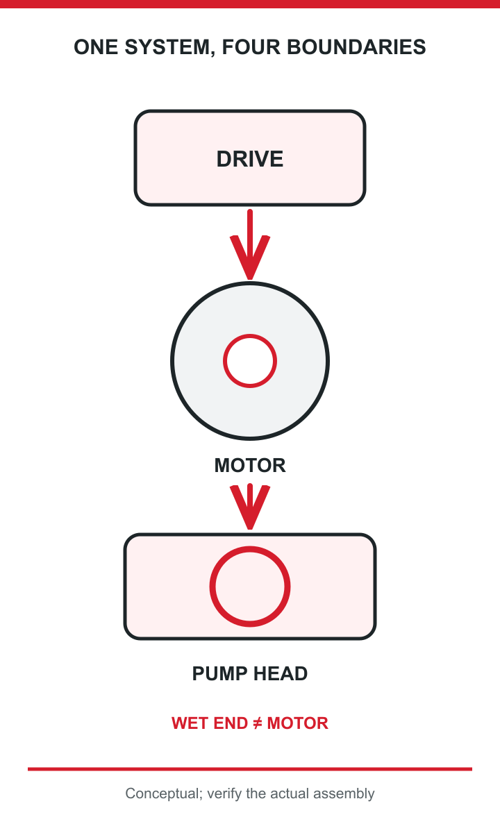
Conceptual engineering diagram; see article text for complete context.
The duty point is the flow the system needs at the total head it imposes. Flow is the volume delivered per unit time; head expresses the energy required to raise and move the liquid through elevation, pressure differences and friction. Record the required flow at the hardest normal operating condition, not merely the maximum flow stated on a listing. Then describe the pipe lengths, bore, fittings, valves, filters and discharge pressure that create the system resistance. The US Department of Energy's centrifugal-pump guidance treats pump and system curves together: the operating point is where the two meet. That is the useful starting point for selecting a pump. A change in pipework, valve position or filter loading can move that intersection after installation. If the system has several modes, give the supplier more than one duty point and indicate which is continuous. Specify the liquid temperature and whether the pump may start against an already pressurised line. At this stage do not convert flow directly into a motor wattage by assuming a universal efficiency. The hydraulic calculation is an input to selecting and testing an actual pump assembly, not a substitute for its curve.
A product may advertise both maximum flow and maximum head. Those values are generally measured under different conditions: unrestricted discharge can produce high flow at low head, while near shut-off can show high head with little useful flow. Reading them as a simultaneous performance point overstates the pump. Request a curve that shows flow against head at the intended speed and liquid conditions, then mark your required point on it. Check whether the curve covers the whole operating range, rather than a single test point. If speed is adjustable, ask for curves or verified data at the speeds you intend to use. The system curve matters too: a duty point close to an extreme may leave little allowance for normal fouling or manufacturing variation. In a variable-resistance circuit, a controller setpoint does not itself guarantee delivered flow. The practical acceptance test is measured flow and pressure in a representative assembly, at temperature and with realistic restrictions. Record the test configuration with the result so a later design change does not make a curve appear valid when it no longer is.
Once the hydraulic assembly and duty range are known, ask what shaft speed and torque the pump requires through that range. Hydraulic output power depends on flow, pressure rise and liquid properties; shaft demand is higher because the pump is not lossless. Electrical input rises again with motor and drive losses. Those relationships explain why a motor rating alone cannot establish delivered hydraulic performance. Use the pump manufacturer's measured curve or engineering model to request a torque-versus-speed duty from the motor supplier. Distinguish continuous duty from startup, priming, short overload and stalled operation. A motor that can briefly start the load may still overheat at a continuous operating point. Conversely, a huge margin can increase package size or cost without improving the hydraulic design. Include ambient temperature, cooling path and enclosure in the assessment because a motor's thermal rating assumes conditions that may not resemble a compact sealed pump. Agree how the assembled product will be tested at its worst credible continuous duty and at transient conditions; document the pass criteria before choosing a catalogue part.
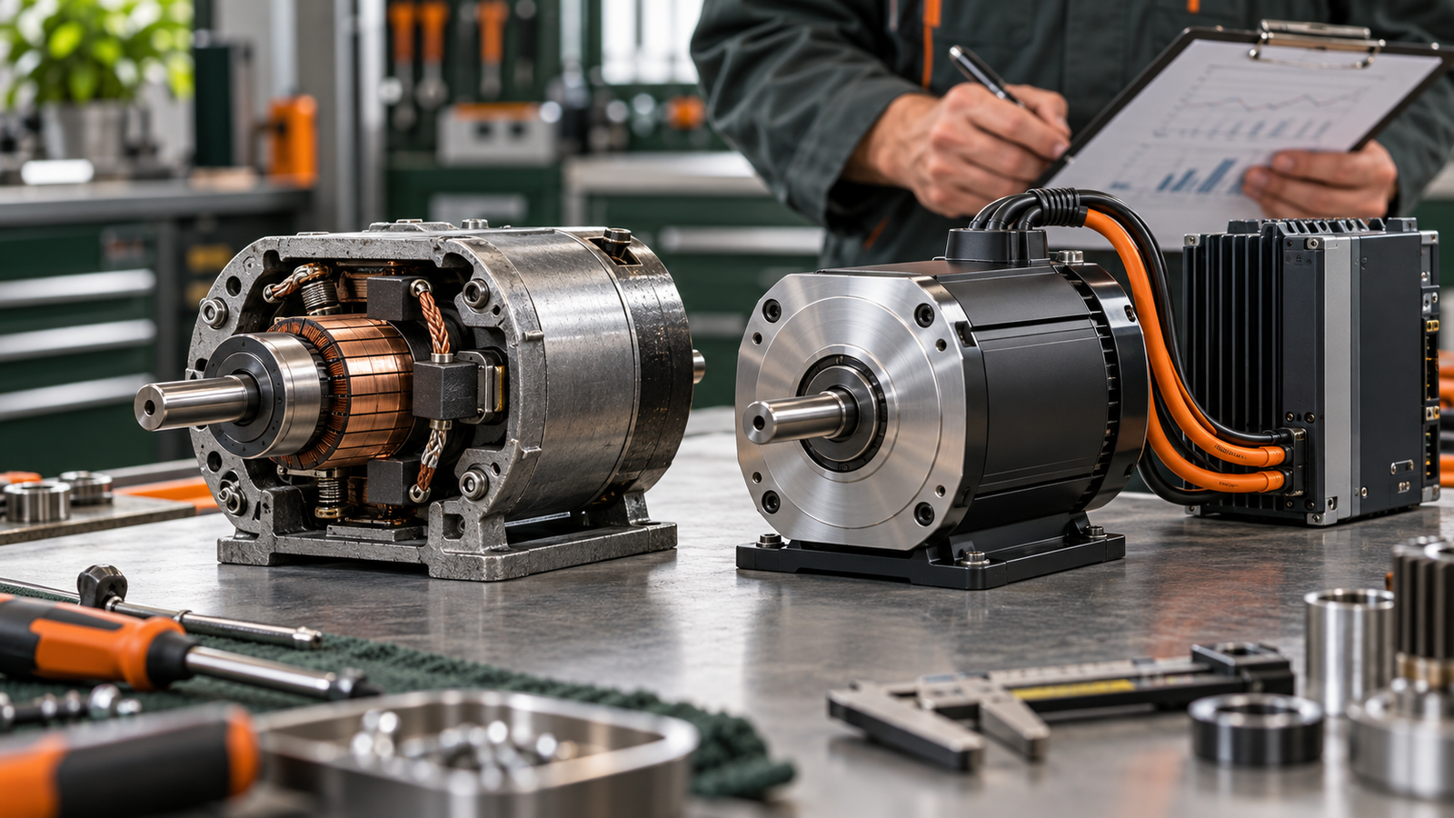
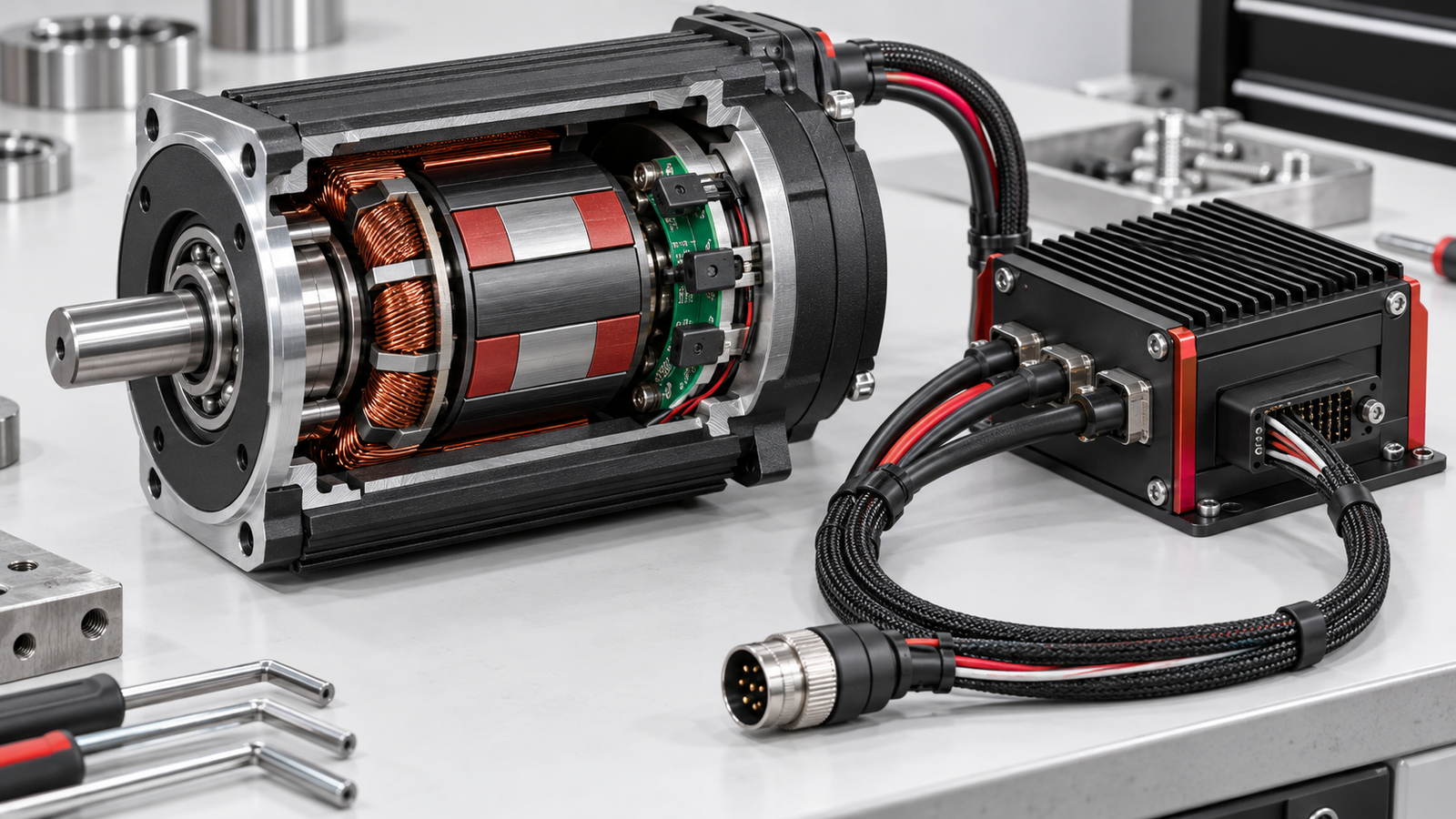
The motor and controller should be specified as one electrical system even when they come from different suppliers. A BLDC motor needs an electronic commutation method; connecting it directly to a DC supply is not the same as operating a brushed DC motor. The drive's voltage and current limits, sensing method, speed range and startup algorithm must fit the selected winding and pump load. Decide whether the product needs a fixed speed, several modes or closed-loop regulation of speed, pressure or flow. That choice determines what feedback is required and what the control system can actually guarantee. A speed command can be precise while flow still changes as the filter clogs or liquid viscosity shifts. Check whether the supply is a regulated DC rail, a battery with a wide voltage range, or power converted from mains or solar input. State expected voltage excursions and wiring lengths rather than only a nominal value. Ask for the permitted motor-drive combinations and test evidence for your operating envelope. For an OEM design, this pairing should be validated on the chosen pump head, not accepted on the basis of motor and controller catalogues separately.

Conceptual engineering diagram; see article text for complete context.
Check the torque the pump needs at startup and throughout the intended speed range, not just at a convenient rated point. Some hydraulic designs start under load; others may run dry briefly or see viscous liquid at low temperature. These cases can demand a different current and thermal response from steady-state circulation. The motor's continuous torque is meaningful only with its specified cooling and ambient temperature. A compact housing can trap heat from both the motor and the controller, while liquid cooling may disappear during dry-run conditions. Request a temperature-rise test at the highest credible continuous load, plus a start and restart test at the supply limits. Include winding, electronics and bearing temperatures where accessible. If the application requires fast changes in speed, evaluate transient current and the mechanical response of the pump. Do not infer that a higher no-load RPM produces more usable flow: the pump curve, load and drive limits determine the operating point. The acceptance question is whether the assembled unit can repeat its required duty without a protection trip or unacceptable temperature rise.
A controller specification should say what happens outside normal operation as clearly as it says how speed is commanded. Define the allowed input range, current limit, stall detection, overtemperature response and restart policy. Decide how the assembly reacts to a blocked outlet, loss of prime, dry running and a disconnected sensor, where those situations are credible. A current limit protects electronics or windings only within a validated thermal scheme; it is not proof that a seal or impeller survives the event. State whether a failed sensor makes the pump stop, revert to a safe fixed speed or alert the host controller. If the machine has multiple pumps, specify how faults are reported and logged. Electromagnetic compatibility and electrical safety requirements depend on the finished product and market, so request model-specific evidence rather than assume a category-wide certification. A bench test should exercise protections with the actual motor, wiring and pump head. Make the trip threshold, response time and recovery behaviour explicit so a supplier's generic phrase such as ‘protected drive’ becomes something you can verify.
The liquid boundary is a separate engineering decision from the motor. The fluid may touch an impeller, housing, shaft, bearing, seal or magnetic coupling depending on construction. A canned or sealless arrangement has different leakage and maintenance implications from a design with a dynamic shaft seal, but neither should be assumed from the word ‘brushless’. Ask for a wet-end drawing or bill of materials showing every contacted material. Then check compatibility with the actual liquid, including additives, cleaning agents and the highest temperature it may reach. Consider entrained particles, viscosity, vapour pressure and whether the pump can be adequately primed. A motor can be electrically well matched while the wet end leaks, cavitates or erodes under real conditions. Graco's discussion of paint-circulation motor selection illustrates why process-fluid systems have constraints beyond motor efficiency; do not transfer its product-specific performance claims to water, coolant or other applications. Establish who supplies and warrants the wet end, and who owns validation of seal life and leakage limits. This is especially important when a motor vendor and pump assembler are different companies.
Fluid compatibility requires a named substance and operating condition, not a generic statement that a pump suits ‘chemicals’. Supply the formulation or material-safety information where appropriate, the concentration range, temperature and cleaning cycle. Verify each wetted material and elastomer against those conditions with the component supplier. The same pump may be suitable for one coolant but unsuitable for a solvent, abrasive suspension or food-contact application. For flammable or hazardous fluids, ordinary catalogue suitability is not enough; classification, electrical protection and the complete installation must be reviewed against the applicable safety requirements by qualified parties. Do not assume that a BLDC motor's lack of brushes makes a finished pump explosion-proof. Likewise, an ingress rating on the motor enclosure does not validate the fluid seal. Request specific test and certification documents for the exact model and assembly, with the intended market and installation method. If those documents are unavailable, mark the application as unverified and do not claim compliance. Treat this as a go/no-go gate before negotiating a motor's marginal efficiency advantage.

Conceptual engineering diagram; see article text for complete context.
Variable speed is useful when required flow or pressure changes enough for the pump to spend meaningful time away from its maximum-duty point, and when control can maintain the process requirement safely. A controller can reduce speed instead of wasting pressure across a throttling valve in some systems. But the energy result depends on pump type, system curve, duty cycle, control losses and the minimum flow or speed the process permits. It is not valid to copy a percentage saving from a different pump or installation. Draw a simple operating profile: hours at each flow and head, starts per hour, and any standby periods. Compare a fixed-speed design with the proposed controlled design over that profile, including the drive's own power and any hydraulic bypass. If the system has a high static-head component, lower speed may cease to deliver the required flow sooner than a casual affinity-law estimate suggests. Confirm stability at low speed and during transitions, as well as adequate cooling. The strongest case for variable speed is a measured or defensibly modelled duty-cycle benefit without compromising the actual hydraulic service.
For example, different applications demonstrate why a single ‘best BLDC pump’ specification is misleading. In a circulation loop, changing resistance from valves or fouled filters may make pressure control and fault detection important. Record the normal and worst-case loop conditions before choosing a motor. In a solar-water application, input power can vary with sunlight; the control system may need to manage low-input startup and operate over a changing supply. BARC's solar BLDC pump work is a useful application example, not a universal sizing table. In paint circulation, fluid properties, cleaning procedures and continuity of production can dominate the selection; Graco discusses this as a process-specific engineering decision. An automotive electric pump may have demanding thermal, supply-transient and diagnostic requirements; STMicroelectronics' automotive control material illustrates the drive side, not approval of a particular pump assembly. For each case, write down the liquid, the hydraulic range, the power supply, the control objective and the required validation. A model tested in one setting should not be called suitable for another solely because both use a brushless motor. The common method is consistent, but the pass criteria are application-specific.
A useful supplier enquiry separates the pump-system requirements from the motor and drive offer. State the liquid and its temperature range, target flow at specified total head, suction conditions, continuous and transient duty, and the intended pump-head type if already selected. Add the available supply range, target speed range, command and feedback interfaces, mounting envelope, noise constraints, expected life and annual quantity. If the pump curve is known, attach it. If not, ask the pump supplier for the curve before treating motor power as settled. Make clear which party owns the wet materials, seal, impeller and complete assembly testing. Request the motor's torque-speed and thermal data, approved drive combinations and protection behaviour at the operating extremes. A sensible comparison records exactly what each quotation includes: motor only, motor plus controller, or tested pump assembly. Finally, define a prototype acceptance plan: measured flow and head, electrical input, temperature rise, startup at voltage limits, leakage and fault responses. This short dossier lets vendors challenge an incorrect assumption early and makes competing responses comparable. It also prevents a cheap bare-motor price from being mistaken for the delivered cost of a qualified pump.

Conceptual engineering diagram; see article text for complete context.
TENCH's first-party catalogue presents brushless motors, gearmotors and related drive categories. That makes TENCH a possible conversation partner for an OEM selecting a motor and controller for its pump design. It does not establish that TENCH supplies a finished BLDC pump, wet-end construction, seal system or certified assembly for a named fluid. An engineering enquiry should therefore focus on the shaft duty, winding and supply, control interface, thermal environment, mounting constraints and forecast volume. TENCH can then identify which documented motor or drive families merit a model-specific review, or say where a requested duty is outside a published range. The pump designer and wet-end supplier still need to verify hydraulic performance, liquid compatibility and complete-product safety. Ask for a written scope of supply and evidence for any claimed rating or certification on the exact proposed model. The practical next step is to send a pump curve or target operating points with the electrical and mechanical boundary; request a scoped motor-and-drive proposal, not a promise that a complete pump will meet its duty. If the system has not yet been hydraulically specified, complete that work first.
Choose a BLDC-driven pump by proving that a complete assembly meets the required flow at head, then verifying that its motor and drive can sustain that duty under the intended electrical, thermal and fluid conditions. The phrase ‘BLDC motor pump’ covers several supply arrangements; confirm whether the offer is a bare motor, a matched motor-drive set or a validated pump assembly. Read a pump curve at the operating point, not two unrelated maximum figures. Test startup, continuous load and fault behaviour on representative hardware. Put liquid compatibility, leakage and applicable safety evidence alongside the electrical specification, because an efficient motor cannot rescue an unsuitable wet end. Variable speed may be worthwhile when the real duty profile supports it, but no generic payback number should replace a system comparison. For a new OEM design, the most useful next action is a concise duty specification and an agreed validation plan. With those in hand, you can ask motor, controller and pump suppliers targeted questions, compare like with like, and keep responsibility for each part of the finished product visible.



Leave a Reply