

Author: Verna Lyu
Technical reviewer: Wen Liu, Engineer
The examples in this article use current TENCH product-family information for initial screening. Final selection still depends on the exact model data and a test in the intended machine.
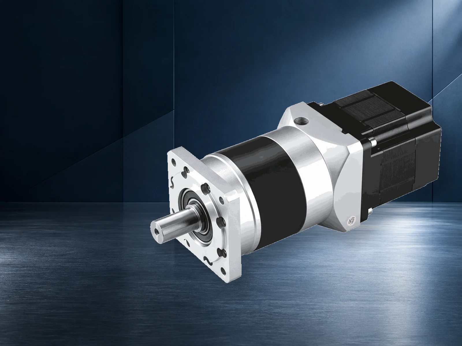
A low-speed BLDC motor should be selected from the machine's minimum stable speed, continuous and peak torque, startup load, speed-regulation requirement, duty cycle and thermal environment. Then decide whether the load should be driven directly or through a gearbox, and match the feedback, controller and power source to that decision.
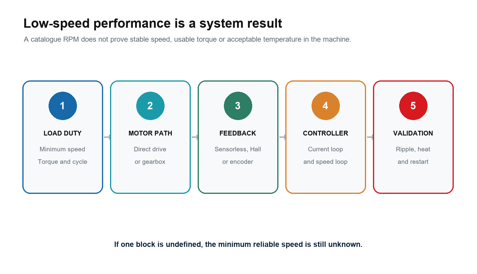
A low catalogue RPM is not enough. A motor may rotate slowly on a bench yet fail to start the real load, hunt around the setpoint, produce unacceptable torque ripple or overheat while holding torque. The useful question is whether the complete motor-drive system can repeat the required low-speed duty with measurable speed quality and acceptable temperature.
Start With the Lowest Required Operating Point
Low speed should be written as a testable operating point, not as an adjective. Record the minimum continuous speed, normal speed range, continuous torque, short-duration peak torque, peak duration, cycles per hour and allowed speed deviation. Add the startup condition, reverse moves, dwell time and any requirement to hold the shaft at zero speed.
| Requirement | What to state | Why it changes the selection |
|---|---|---|
| Minimum stable speed | Loaded shaft rpm and permitted ripple or deviation | Sets the feedback resolution, control method and gearbox decision |
| Startup and restart | Load torque, inertia, permitted reverse movement and required start time | Exposes sensorless-start and current-limit risks |
| Continuous torque | Torque at the minimum and normal running speeds | Sets current and thermal demand |
| Peak torque | Magnitude, duration, repetition and starting temperature | Sets short-term motor, controller and gearbox limits |
| Zero-speed duty | Holding time, disturbance torque and safety function | May require current, a brake, a counterbalance or another holding mechanism |
| Speed quality | Ripple, settling time, repeatability and disturbance recovery | Determines whether Hall feedback is sufficient or an encoder is required |
Also define the real DC-bus range, ambient temperature, enclosure, mounting surface, airflow, cable length and available controller interfaces. A requirement such as '10 rpm under a 0.8 N·m load with less than 2% steady speed variation after a 0.2 N·m disturbance' can be tested. 'Very slow and smooth' cannot.
Can a BLDC Motor Run at Low Speed
Yes, a BLDC motor can produce torque at low speed when the controller knows the rotor position well enough and can regulate the required current. Within the motor's magnetic and thermal limits, electromagnetic torque is related to torque-producing current. Low speed does not remove the need for current; it only reduces mechanical output power for the same torque.
At zero speed, mechanical output power is zero, but winding current can still create copper loss. That is why a motor can become hot while holding a stationary load. At low running speed, iron losses may fall, but copper loss can remain high when the load requires substantial torque. The mounting and cooling path therefore remain part of the rating.
Smoothness also depends on motor construction, commutation, current regulation and the mechanics attached to the shaft. Cogging torque, six-step commutation ripple, gearbox backlash and a compliant coupling can all become more visible at slow speed. A motor described as brushless or slotless does not by itself prove a minimum stable rpm or a speed-ripple value.
Choose Feedback From Startup and Speed Quality
Basic back-EMF sensorless control has the least position information at standstill and very low speed because back EMF is proportional to speed. Microchip's sensorless BLDC guidance explains that the controller normally uses an open-loop start until the signal is large enough for position estimation. Maxon's sensorless-control guidance makes the same boundary clear: a back-EMF method cannot provide defined speed and torque control at zero or low speed.
| Position or speed source | What it can provide | Low-speed use | Questions to verify |
|---|---|---|---|
| Basic back-EMF sensorless | Estimated commutation timing after the motor is rotating | Suitable only when startup and the minimum running speed are validated for the load | Open-loop start, takeover speed, reverse behavior, load sensitivity and restart |
| Hall sensors | Discrete rotor sectors for commutation | Often practical for loaded start and ordinary low-speed operation | Hall order, alignment, logic level, electrical angle, noise immunity and achievable speed ripple |
| Incremental or absolute encoder | Finer rotor or output-shaft position information | Useful when tighter speed regulation, repeatability or position-related functions are required | Interface, resolution, index or absolute data, maximum frequency, mounting, alignment and cable shielding |
| Advanced sensorless estimator | Rotor angle estimated from a motor model and measured electrical behavior | May extend low-speed capability when supported by the exact controller and motor | Required motor parameters, current sensing, tuning, load range and minimum validated speed |
Hall sensors are not automatically equivalent to a high-resolution encoder. Three Hall devices commonly provide discrete commutation sectors, which may be enough for starting and basic speed regulation but not for a demanding low-speed ripple or position requirement. An encoder adds information only if the controller accepts that interface and uses it in the required control loop.
If a gearbox sits between the motor and load, decide where feedback belongs. A motor-side encoder measures the motor and benefits from the gear ratio, but it does not directly observe gearbox backlash, torsional compliance or output-shaft movement. An output-side encoder can measure the load more directly, although it adds mechanical and control complexity. The control architecture must define which signal closes which loop.

Match the Controller and Control Method
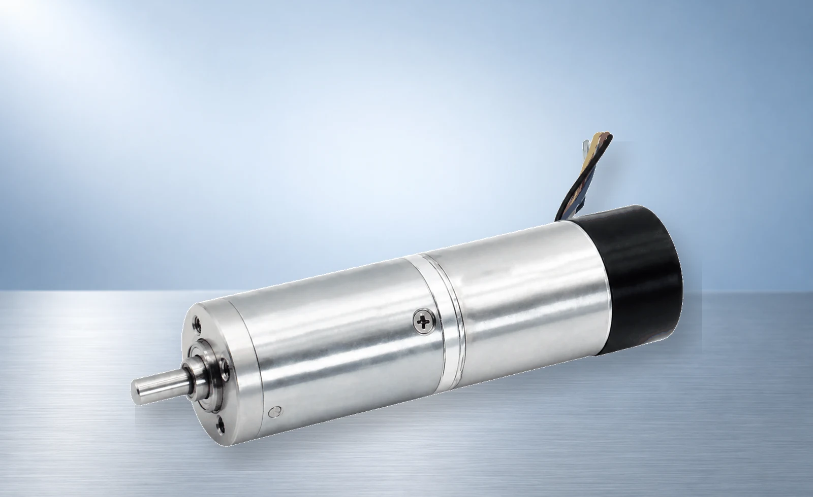
The controller determines whether the available feedback becomes useful low-speed performance. Confirm the motor phase configuration, pole pairs, resistance, inductance, back-EMF behavior, Hall sequence or encoder interface, DC-bus range, continuous and peak phase-current limits, electrical-frequency limit and supported control modes. The current definitions must match; DC-bus current, phase RMS current and phase peak current are not interchangeable.
Six-step commutation can be suitable when its loaded start, minimum speed, ripple and acoustic result meet the machine requirement. Field-oriented control can improve current regulation and torque smoothness when the motor data, current sensing, rotor-angle information and tuning are correct. FOC is not a guarantee. A poorly tuned loop, coarse position signal or inadequate current measurement can still produce unstable low-speed motion.
Check command resolution and loop behavior as well as the power stage. A coarse analog command, noisy potentiometer, slow communication update or poorly scaled speed reference can make the motor appear unstable even when the rotor feedback is adequate. Verify current-loop and speed-loop tuning under the real inertia, friction and gearbox compliance. Use the BLDC motor controller selection guide for the full voltage, current, feedback, braking, protection and interface review.
Decide Between Direct Drive and a Gearmotor
A gearbox is often the practical way to obtain a low output speed while keeping the motor in a more useful speed range. The initial ratio estimate divides the expected loaded motor speed by the required output speed. Choose an available catalogue ratio, then recalculate speed and torque with the exact gearbox data.
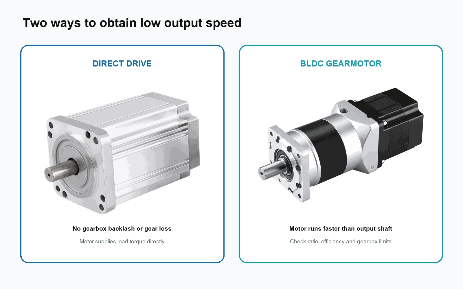
Gearbox efficiency must come from the selected ratio and gearbox documentation. The gearbox also has its own continuous and intermittent torque, maximum input speed, radial load, axial load, backlash, noise, lubrication and service-life limits. A higher ratio does not authorize unlimited output torque.
| Decision point | Direct-drive BLDC | BLDC gearmotor |
|---|---|---|
| Minimum output speed | Depends strongly on feedback, controller and thermal design | Motor can run faster while the output shaft runs slowly |
| Required motor torque | Motor carries the load torque directly | Ratio multiplies output torque after gearbox losses |
| Backlash | No gearbox backlash | Depends on gearbox type, ratio, wear and assembly |
| Efficiency | No gear-mesh loss | Gearbox loss depends on type, stages, load and lubrication |
| Package and current | May require a larger motor and higher current | Can reduce motor torque demand but adds gearbox length and limits |
| Validation | Speed ripple, current, temperature and mounting | All direct-drive checks plus gearbox temperature, noise, backlash and shaft loads |
A Ratio Screening Example
Suppose a machine needs 60 rpm at the output shaft and the candidate motor is expected to run near 3,000 rpm under load. The first ratio estimate is 3,000 ÷ 60 = 50. A 50:1 ratio is only a starting point. The engineer still has to confirm that the selected gearbox offers that ratio, calculate the motor torque from the load and the documented efficiency, and verify continuous torque, peak torque, shaft loads and actual loaded speed.
Do not use the motor's no-load speed as the final design speed. Controller limits, voltage drop and load can reduce motor speed. TENCH gearmotor pages also note that actual output speed can be lower than the simple nominal-speed calculation under load. Use How to Size a BLDC Gearmotor for the complete load-side process.
Check Thermal Limits at Low Speed and Standstill
Portescap's thermal guidance separates joule loss from iron loss. High torque at low speed can produce substantial winding loss, while iron loss generally grows with speed. The motor must keep its winding below the permitted temperature in the actual mounting and ambient conditions. A lower shaft speed does not make the thermal check optional.
Cooling assumptions can also change with speed. If the motor or assembly relies on a shaft-driven fan, lower speed reduces airflow. If it is sealed inside a compact enclosure, heat may be trapped. A conductive mounting plate can improve heat transfer, while a higher protection configuration may change it. Apply only the exact model's documented rating and derating method.
For continuous low-speed duty, run the representative load until temperatures stabilize or until a validated thermal model identifies the worst point. For repeated starts and reversals, begin from the hottest credible condition and repeat the full cycle. Monitor the motor, controller and gearbox. A five-minute bench run is not evidence for an eight-hour duty.
Set Measurable Low-Speed Acceptance Criteria
A minimum rpm figure is incomplete without a quality limit. Define how the machine will be judged at that speed. Useful criteria include steady-state speed deviation, peak-to-peak ripple, settling time after a load step, restart time, permitted reverse movement, acoustic level, vibration and the temperature reached after the complete duty cycle.
- Start from the worst credible rotor position and supply voltage under the real load.
- Run at the minimum speed after the motor and controller are warm, not only from a cold start.
- Apply the expected disturbance torque and record speed drop and recovery time.
- Test forward-to-reverse transitions and every required restart condition.
- Repeat the full duty until motor, controller and gearbox temperatures stabilize.
- Record the controller settings, firmware, feedback device, load, supply and ambient condition with the result.
Use TENCH Product Data as a Starting Point
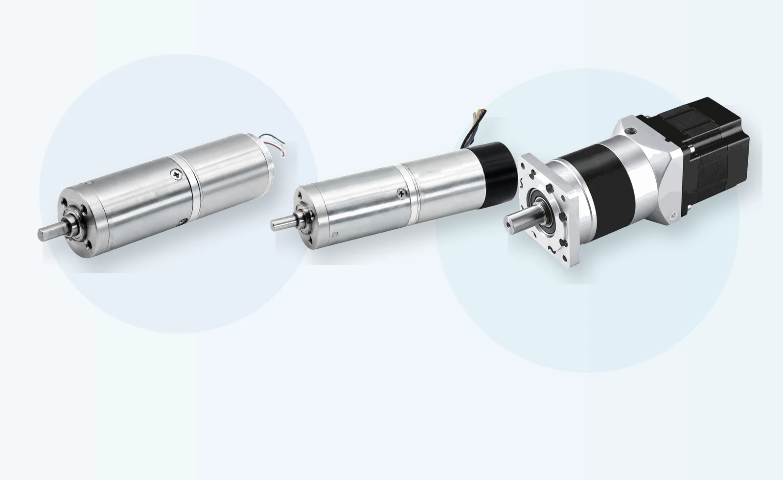
TENCH publishes direct-drive BLDC motors, standard and planetary BLDC gearmotors, micro BLDC gearmotors and low-voltage controllers. These categories offer several starting architectures, but the product-family name does not approve a low-speed duty. The selected winding, ratio, feedback and controller must come from compatible model data.
| TENCH starting path | Published product facts | How to use the information |
|---|---|---|
| TCK1625-PG16 micro planetary gearmotor | 12 V or 24 V, 5 W or 12 W, ratios 4:1 to 3,027:1; published rated output speeds include 4 to 5,500 rpm depending on version and ratio | Shortlist compact geared outputs, then use the exact ratio row for torque, speed, efficiency and length |
| TCK1625-E-PG16 with magnetic encoder | Magnetic encoder with 8 to 2,048 PPR options, SPI and ABZ outputs, 3.0 to 5.5 V encoder supply | Use when the controller and application need the supported feedback; do not copy motor performance from the non-encoder page without confirmation |
| TC5 and TC6 86 mm BLDC gearmotor families | Current category listings include 90 W to 750 W variants and multiple reduction ratios | Review for higher-power low-speed output, then check the exact motor, gearhead, ratio and permissible gearbox torque |
| High-power BLDC motor families | Frame, voltage, power and rated-speed ranges vary by series | Review for direct-drive or custom motor paths only when the exact torque-speed and thermal data support the low-speed point |
| BLD and TCBLD controller families | Model-dependent voltage, current, feedback and interface options | Confirm the exact motor-controller code, current definitions, feedback interface and minimum validated speed |
The TENCH TCK1625-PG16 product page is a useful example of ratio-specific data. Its table does not treat every ratio as equally efficient or capable of unlimited torque. That is the correct way to use a gearmotor catalogue: select one row, keep its units and limits together, and avoid combining the highest value from several rows.
Follow an Eight-Step Selection Process
- Define the minimum and maximum loaded speed, continuous torque, peak torque with time, startup load, reversals, duty cycle and any zero-speed holding requirement.
- Set measurable motion criteria, including speed ripple, allowable deviation, settling time, restart behavior, acoustic noise and vibration where they matter.
- Choose the mechanical architecture. Compare direct drive with the available gear ratios, gearbox efficiency, backlash, shaft loads and package size.
- Choose rotor information from the duty. State whether basic sensorless control, Hall sensors, a motor encoder or output-shaft feedback can satisfy the startup and low-speed requirement.
- Match the controller to the exact motor. Check bus voltage, phase-current definitions, continuous and peak current, commutation or FOC support, feedback interface, command resolution and protection.
- Check thermal and environmental conditions at low speed. Include mounting, enclosure, airflow, ambient temperature, dust, moisture, cable length and adjacent heat sources.
- Plot or tabulate every required operating point against exact motor and gearbox limits. Keep continuous, transient and fault conditions separate.
- Validate the assembled machine from cold and hot conditions, then record the hardware, software, settings, load and acceptance results.
If the project also needs unusually high shaft torque, use the high-torque BLDC motor selection guide to check continuous, peak and stall definitions. The two topics meet at the operating point, but they answer different questions: this page defines reliable motion near the minimum speed; the torque guide defines the motor and system limits needed to produce the load torque.
Send Complete Data to the Motor Supplier
- minimum, nominal and maximum loaded shaft speed
- continuous torque and every peak torque with duration and repetition
- startup load, static friction, inertia, reversals and permitted reverse movement
- steady speed deviation, ripple, settling time and position or repeatability requirement
- direct-drive or gearbox preference, output-shaft loads, backlash limit and package envelope
- minimum, nominal and maximum DC-bus voltage plus available current
- Hall, encoder or sensorless requirement and the controller interface
- ambient temperature, enclosure, cooling, ingress protection and cable length
- duty cycle, starts per hour, zero-speed holding time and braking requirement
- prototype quantity, annual volume and the planned acceptance test
This information lets the supplier screen one motor, one winding, one feedback arrangement, one controller and one gearbox row. It also exposes missing data before a sample is ordered. Send the specification through the engineering enquiry form when requesting a TENCH review.
Frequently Asked Questions
Can a BLDC motor run at 1 rpm?
Possibly, but the motor label cannot answer the question. One rpm under load may require high-resolution feedback, a compatible controller, suitable tuning and a gearbox. Define torque, speed ripple, startup and temperature, then test the exact motor-drive system.
Why does a sensorless BLDC motor struggle at low speed?
A basic back-EMF method relies on voltage generated by rotor motion. That signal approaches zero at standstill and becomes small and noisy at low speed. The controller therefore needs an open-loop start or another estimation method, and the minimum loaded speed must be validated.
Are Hall sensors enough for low-speed control?
They may be enough for loaded starting and ordinary speed regulation. Their discrete electrical sectors may be too coarse for tight speed ripple, fine positioning or demanding repeatability. Check the controller's Hall processing and the machine acceptance criteria.
Does an encoder always improve low-speed performance?
Only when its resolution, interface, mounting and signal quality match the controller and the controller uses it in the relevant loop. A motor-side encoder also does not directly measure gearbox backlash or output-shaft motion.
Is a gearbox always required for a low-speed BLDC motor?
No. Direct drive can avoid backlash and gear loss when the motor, feedback, controller and thermal design can deliver the required torque and speed quality. A gearbox is often practical when output speed is far below the motor's useful range or when compact output torque is important.
Why can a motor heat up while holding at zero speed?
Current can produce torque and copper loss even when the shaft is stationary. Mechanical output power is zero at zero speed, so holding torque must be checked as a thermal duty. Safety-related holding may also require a mechanical brake or another independent measure.
Specify the Low-Speed Duty Before Choosing the Motor
Reliable low-speed motion comes from a defined operating point and a matched system. Write down the minimum loaded speed, torque, startup condition, speed quality, duty cycle and temperature limits. Then choose direct drive or a gearbox, select the feedback and controller, and verify the exact model data.
Treat the supplier's catalogue as a shortlist, not an approval. A successful prototype should start from the worst credible condition, hold the minimum speed under load, recover from disturbances and complete the full hot duty without exceeding the motor, controller or gearbox limits. Those test results, recorded with the exact configuration, are the evidence that the low-speed BLDC system is ready for the machine.
Technical References
- Microchip Developer Help, How Sensorless BLDC Motors Work.
- Microchip AN1083, Sensorless BLDC Control with Back-EMF Filtering.
- Texas Instruments, Brushless-DC Motor Driver Considerations and Selection Guide.
- maxon Support, Applications and Restrictions of Sensorless Control.
- Portescap, Thermal Considerations for Ironless Brush DC and Brushless DC Motors.
- ElectroCraft, Selecting a Brushless DC Motor or Gearmotor.
- TENCH, TCK1625-PG16 Product Page.

Leave a Reply